10-Position 3.5mm Terminal Block Plug: Application Guide & Best Practices
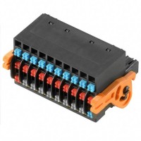
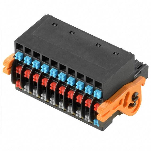
For the Weidmüller TERM BLOCK PLUG 10POS STR 3.5mm (SKU: 1000570000), recommended circuit topologies primarily involve its use as a field-side interface for discrete wiring in control, sensor, and power distribution applications. This plug is designed for a 3.5mm pitch, making it ideal for compact signal-level connections, typically up to 8A and 150V. The most practical topology is a point-to-point connection between a field device and a PCB-mounted header. For best results, always pair this plug with a compatible Weidmüller header of the same pitch and pin count. In multi-signal applications, consider grouping related signals (e.g., all inputs for a single sensor) on adjacent pins to simplify wiring and troubleshooting. Avoid using this plug for high-frequency signals above a few MHz due to its unshielded, screw-clamp construction; for such cases, use a dedicated coaxial or twisted-pair connector. A key design best practice is to always include a strain relief mechanism, either through the built-in clamping on the plug itself or by securing the cable bundle externally, to prevent mechanical stress on the solder joints.
Component selection guidelines for supporting passives are critical to ensure reliable operation. For each signal line connected to the plug, consider series resistors (10-100 ohms) for current limiting or signal damping, especially if the wire run is long (>1 meter). Place these resistors as close as possible to the plug pins on the PCB. For ESD protection, add TVS diodes (e.g., 5V or 24V bidirectional, depending on your signal voltage) between each signal pin and ground, with minimal trace length to the TVS. For power supply inputs, use a ferrite bead in series with the power pin followed by a bulk capacitor (10-100 µF) and a 0.1 µF ceramic capacitor to ground. The ceramic capacitor must have a voltage rating at least double the expected voltage. For analog signals, use a 1 nF to 10 nF capacitor to ground at the plug pin to filter high-frequency noise, but ensure this does not unduly load the signal source. Always choose capacitors with X7R or C0G dielectrics for stability, and ensure all passives are rated for at least 85°C to match the plug's operating temperature range.
PCB layout recommendations and routing tips start with the physical footprint. Use a through-hole layout for the mating header, with plated through-holes of at least 0.8mm diameter and 1.6mm annular ring for reliability. Orient the plug so that the wire entry is parallel to the board edge for easy access. Route traces from the header pins with a width of at least 0.3mm for 1A current, increasing to 0.5mm for 4A. Keep analog and digital signals separated; route all digital lines on one side of the header and analog on the other, with a ground trace between them. For differential signals, route them as a closely coupled pair from the plug to the first active component. Avoid routing high-speed traces (e.g., SPI, I2C) directly under the plug's screw terminals, as the unshielded wires can couple noise. Place a solid ground plane on an inner layer directly under the plug area, with no splits, to provide a low-impedance return path. Add a grounded copper pour on the top layer around the header pins, but leave a 0.2mm clearance to each pin to avoid solder bridging.
EMC/EMI considerations and mitigation strategies are essential for this plug, as it connects to external wiring which acts as an antenna. The primary mitigation is to use a common-mode choke on the cable side for all signals, especially if the cable length exceeds 3 meters. Place this choke inside the enclosure, close to the plug. For conductive emissions, add a 1-10 nF capacitor from each signal line to chassis ground at the plug, but only if the signal frequency is below 1 MHz to avoid ground loops. For radiated emissions, ensure the cable shield (if used) is connected to chassis ground at the plug entry point via a 360-degree clamp, not a pigtail. On the PCB, use a ferrite bead on the ground pin of the plug to isolate the external ground from the internal digital ground, but only if the system uses a single-point ground scheme. For systems with multiple plugs, keep each plug's wiring bundle twisted and separated by at least 5mm from other bundles to minimize crosstalk. Finally, always include a 100-ohm resistor in series with any connector pin that carries a clock signal above 10 MHz to dampen ringing.
Common design pitfalls and how to avoid them include: first, using the plug for high-current loads—this plug is rated for 8A max per contact, but derate to 5A if all 10 positions are fully populated. Second, failing to properly torque the screw clamps; use a calibrated screwdriver set to 0.2 Nm to avoid stripping the threads or damaging the wire. Third, improper wire strip length—strip exactly 7mm of insulation, no more, to ensure the conductor is fully clamped without exposing bare wire beyond the terminal. Fourth, mixing wire gauges in adjacent positions; use the same gauge (0.14-1.5 mm²) for all wires to maintain consistent clamping force. Fifth, ignoring pin numbering on the plug—always verify the orientation of the plug relative to the header by marking pin 1 on both the PCB silkscreen and the plug housing. Sixth, subjecting the plug to vibration without a locking mechanism; use Weidmüller's optional locking flanges or a dab of thread-locking compound on the screws. Finally, test for intermittent connections by wiggling each wire after initial assembly.
Prototyping tips and bench testing procedures begin with a visual inspection: check that all screw clamps are closed, no solder bridges exist on the header, and the plug is fully seated with an audible click. For electrical testing, use a multimeter in continuity mode to verify each pin from the wire tip to the PCB test point. Then, apply a low DC voltage (e.g., 5V) through one wire and measure the voltage drop across the plug's contact resistance; it should be less than 5 mV at 1A. For signal integrity, inject a 1 MHz square wave through the plug and observe the waveform on an oscilloscope; look for overshoot, ringing, or noise pickup. For EMC pre-compliance, use a handheld near-field probe to scan the plug and wiring for emissions at the fundamental frequency. During prototyping, always leave room on the PCB for additional filter components (e.g., unpopulated 0805 pads for series resistors and shunt capacitors). Finally, perform a thermal test by running the maximum rated current through all 10 positions simultaneously for 30 minutes, monitoring the temperature rise at the plug body; it should not exceed 40°C above ambient. Document all test results for the final design validation report.