MC9S12XDT512MAA Reliability Guide: Maximizing MCU Performance
This guide addresses the critical reliability and quality assurance aspects for the NXP MC9S12XDT512MAA, a 16-bit microcontroller with 512KB Flash in an 80-pin QFP package. As a professional procurement component, its reliability is paramount for long-life applications in automotive, industrial, and medical systems. The following sections outline the key areas for ensuring dependable operation.
Reliability Standards and Qualifications
This NXP MCU is typically qualified to AEC-Q100 (Automotive Electronics Council) standards, which is the definitive stress test qualification for integrated circuits used in automotive environments. This includes rigorous temperature cycling, high-temperature operating life (HTOL), and ESD (Electrostatic Discharge) testing. For industrial applications, it may also comply with JEDEC standards such as JESD47. The component's datasheet and NXP's qualification report should confirm the specific grade, usually Grade 1 (operating temperature range -40°C to +125°C). Always verify that the procurement batch includes a Certificate of Conformance (CoC) referencing these standards.
Accelerated Life Testing (ALT) and Results Interpretation
Accelerated life testing for this MCU involves subjecting devices to higher temperatures and voltages to accelerate failure mechanisms. Common tests include High-Temperature Operating Life (HTOL) at 125°C or 150°C for 1000 hours. The results are used to model the device's lifetime under normal conditions using an Arrhenius equation. A typical result might show a projected lifetime of 10-15 years at 85°C junction temperature. Interpretation is critical: a low failure rate in ALT (e.g., 0 failures out of 1000 units) does not guarantee zero field failures but provides a statistical confidence bound. A failure during ALT, such as a memory bit error or EEPROM retention loss, indicates a potential weakness that must be assessed against the application's mission profile.
Failure Rate Calculations (FIT Rates) and MTBF Considerations
The Failure In Time (FIT) rate for the MC9S12XDT512MAA is typically very low, often cited in the range of 10-50 FIT (failures per 10^9 device-hours) under controlled conditions. This translates to a Mean Time Between Failures (MTBF) of 20 to 100 million hours. However, these numbers are derived from reliability prediction models (e.g., Telcordia SR-332 or MIL-HDBK-217) and assume ideal operating conditions. Real-world MTBF is lower due to voltage stress, thermal cycling, and manufacturing defects. For procurement, request the supplier’s FIT data from actual qualification testing, not just predictive models. A common mistake is using a single FIT value; consider the mission profile (duty cycle, ambient temperature) to adjust the effective failure rate.
Environmental Stress Screening (ESS) and Burn-In Procedures
Burn-in for this MCU is not mandatory for all applications, but it is highly recommended for safety-critical or high-reliability projects. Typical burn-in involves operating the device at 125°C for 48-168 hours with dynamic voltage and clock cycling to activate latent defects. Environmental stress screening (ESS) may include temperature cycling from -40°C to +125°C for 20-50 cycles and random vibration. For procurement, specify burn-in if the application demands zero infant mortality. The supplier or a third-party test house can perform this. Note that excessive burn-in can actually degrade the device (e.g., electromigration in interconnects), so follow NXP’s recommended stress limits. Post-burn-in electrical testing is essential to confirm functionality.
Counterfeit Detection Methods Specific to This Component Type
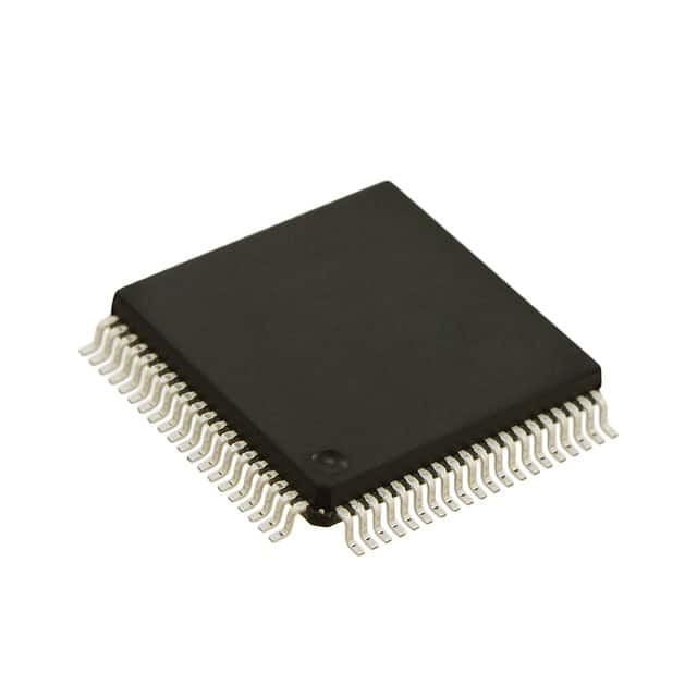
The MC9S12XDT512MAA is a mature part and a target for counterfeiting due to its widespread use. Counterfeit detection must include multiple layers. First, visual inspection of the 80-QFP package: genuine NXP parts have precise laser marking, uniform lead finish (typically tin-plated) with no pitting or discoloration, and consistent mold compound texture. Second, electrical testing: perform parametric tests (e.g., supply current, leakage currents on I/O pins) and functional tests (e.g., writing to Flash memory and reading back) to verify performance against datasheet limits. Third, X-ray inspection can reveal missing or misaligned bond wires or die size inconsistencies. For higher confidence, use decapsulation and SEM analysis to inspect the die markings and structure, comparing them to known genuine samples. Always source from authorized distributors to minimize risk.
Incoming Inspection Best Practices
Incoming inspection should follow a documented procedure. Begin by verifying the part number, date code, and lot number against the purchase order. Perform visual inspection under 10x-30x magnification for package damage, lead coplanarity, and marking legibility. Use a digital micrometer to check package dimensions (QFP body size is typically 14mm x 14mm). Next, conduct electrical verification using a functional test fixture or a known-good programming setup to read the device ID and flash memory. For high-volume procurement, sample testing per AQL (Acceptable Quality Level) standards like ANSI/ASQ Z1.4 is acceptable, but for critical applications, consider 100% inspection. Document all results to create a traceable quality record.
Storage and Handling Requirements to Maintain Reliability
This MCU is sensitive to moisture. It arrives in a moisture-sensitive device (MSD) packaging, classified as MSL (Moisture Sensitivity Level) 3 typically. Storage must be in a dry environment (relative humidity <60%) or in a moisture barrier bag with desiccant and humidity indicator card. Once the bag is opened, the floor life is 168 hours at ≤30°C/60% RH. If this time is exceeded, the components must be baked before soldering (e.g., 24 hours at 125°C). Handling requires ESD protection: use grounded wrist straps, conductive workstations, and anti-static bags. Never touch the leads directly to avoid contamination or corrosion. For long-term storage (over 6 months), re-seal in a dry bag with fresh desiccant.
End-of-Life Management and Obsolescence Planning
The MC9S12XDT512MAA is a mature product, and NXP may issue an end-of-life (EOL) notice at any time. Proactive obsolescence planning is critical. Monitor NXP’s product change notifications (PCNs) and EOL notifications quarterly. If an EOL is announced, you typically have a 6-12 month last-time buy (LTB) window. Place a strategic LTB order to cover your remaining production needs and spare parts for 2-5 years. Consider second-sourcing with a similar NXP device (e.g., MC9S12XEP100) or a migration to a newer family like S32K. Qualify a backup device in advance to avoid last-minute redesigns. For legacy systems, use a reliability prediction to estimate when field failures may cause support issues, and plan a phased replacement.