Mastering SMD Rework: WTHA1N 900W Station Application Guide
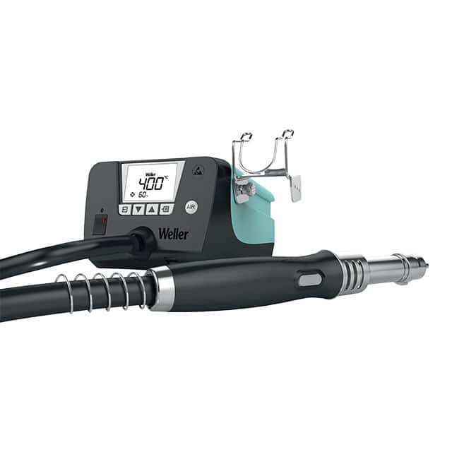
The Apex Tool Group WTHA1N 900W 1-Channel 120V rework station is a high-power tool designed for professional through-hole and surface-mount soldering and desoldering. When integrating this station into a production line or a dedicated bench setup, the primary considerations are not traditional circuit topologies in the sense of an amplifier or power supply, but rather the topology of the power distribution and control system that supports the station. The recommended topology is a dedicated, isolated branch circuit. This station draws up to 7.5A continuously, and inrush current can be higher. Therefore, a circuit breaker rated for 15A minimum is essential, with a dedicated neutral and hot wire running directly from the main panel to the workstation outlet. Best practices dictate that this circuit should not share a common neutral with other high-load equipment like compressors or large motors, as this can introduce ground loops and voltage dips that affect the station’s microcontroller and temperature sensing accuracy. For the control interface, a simple SPST relay or solid-state relay (SSR) can be used for remote on/off control via a foot pedal or PLC, but this should be wired with a flyback diode (for relay coils) or a snubber circuit (for SSRs) to prevent inductive kickback from damaging the station’s internal logic.
Component selection guidelines for supporting passives are primarily focused on the external ESD-safe workstation and any custom fume extraction or footswitch system. For the footswitch, select a heavy-duty momentary switch rated for at least 10A at 125VAC, such as a metal-enclosed industrial foot pedal. The connecting cable should be a three-conductor 14 AWG SOOW or SJTOW cord for durability. If integrating the station into an automated pick-and-place line, the remote interlock input often requires a dry contact closure. Use a sealed, gold-plated relay for this contact to ensure low resistance and high reliability over thousands of cycles. For any local EMI filtering on the station’s input, a standard IEC inlet filter with a rated current of 10A and an attenuation of at least 30dB at 150kHz is recommended, though the WTHA1N likely has internal filtering. The most critical passive component is the grounding wire. Use a dedicated, low-impedance earth ground connection via a 10 AWG or larger green wire to the station’s chassis ground screw. This is non-negotiable for safe operation and to prevent electrostatic discharge (ESD) damage to sensitive components being reworked.
PCB layout recommendations and routing tips apply to the design of the user’s own control board or interface circuit. If building a custom controller to sync the station with a reflow oven or pick-and-place machine, keep the high-current AC traces (120V, 7.5A) on a separate layer from the low-voltage DC control signals. Use a minimum trace width of 150 mils for 2 oz copper on the AC path to avoid overheating. Route the microcontroller’s I/O lines (for temperature setpoint or status LEDs) as differential pairs with a ground plane underneath to minimize noise coupling from the station’s high-power heater cycles. Place the relay or SSR that controls the station’s power physically as close to the AC inlet as possible, with a dedicated thermal relief pad on the high-current side. For the footswitch connector, use a polarized header and route the two wires as a tightly twisted pair away from any high-frequency switching nodes. Avoid running the AC neutral and hot wires parallel to any sensor lines for more than 1 inch; if crossing is unavoidable, do so at 90 degrees to minimize capacitive coupling.
EMC/EMI considerations and mitigation strategies are critical because a 900W heater with a thyristor or triac control circuit can generate significant conducted and radiated emissions. The WTHA1N’s internal circuitry likely includes a snubber across the heater element, but external mitigation is still prudent. Install a ferrite core (e.g., a split-core ferrite with an impedance of at least 200Ω at 100MHz) on the AC power cord directly after the plug, wrapping the cord through the core three turns. This attenuates common-mode noise from the heater switching. For radiated emissions, ensure the workstation’s metal chassis is bonded to earth ground with a low-inductance strap (e.g., a braided copper strap) rather than a thin wire. If the station is used near sensitive RF circuits (e.g., in a test lab), place a line filter with both common-mode and differential-mode chokes on the AC input, such as a Schaffner FN2030 series rated for 10A. Additionally, avoid running the station’s power cord parallel to any data cables or signal lines for more than a few inches; maintain a 6-inch separation. For the footswitch cable, use a shielded twisted pair with the shield grounded only at the station end to prevent ground loops.
Common design pitfalls and how to avoid them include undervoltage operation, thermal runaway in the handpiece, and ESD damage to the station’s controller. A frequent mistake is plugging the station into a power strip with other high-draw equipment, causing voltage sag during heater cycles that can corrupt the microcontroller’s temperature PID loop. Always use a dedicated outlet. Another pitfall is using an undersized or oxidized tip in the handpiece, which can cause the heater to run continuously to compensate for poor thermal transfer, leading to premature failure. Always use genuine Apex Tool Group tips with the correct thermal profile. A third pitfall is neglecting the ESD grounding path. The station’s handle is grounded through the power cord only if the outlet is properly grounded. Test the outlet with a plug-in tester before use. Finally, do not attempt to modify the station’s internal wiring or bypass the safety thermocouple; this can cause the heating element to overheat and melt the handpiece. If the station fails to reach temperature, check the tip for oxidation or the thermocouple connection before assuming a component failure.
Prototyping tips and bench testing procedures should focus on verifying proper operation before committing to a production setup. Begin by measuring the AC voltage at the outlet under load using a true RMS multimeter while the station is heating a large ground plane. Ensure voltage stays above 115VAC. Then, perform a temperature accuracy test using a calibrated thermocouple meter attached to the tip. Set the station to 350°C and measure the tip temperature after 30 seconds of stabilization; the reading should be within ±10°C. For the footswitch or remote control, simulate the contact closure with a short piece of wire and confirm the station’s heater power cycles on and off. Test the ESD grounding by measuring resistance from the station’s handle to a known earth ground point; it should be less than 1 ohm. For a final prototyping run, rework a test board with known solder joints and inspect for cold joints or lifted pads. Document the tip temperature profile and the station’s recovery time after the first joint. If the recovery time exceeds 5 seconds, consider using a larger tip or reducing the thermal mass of the board. Always allow the station to cool down completely before storing, and use a tip cleaner with a brass coil rather than a wet sponge to avoid thermal shock to the tip.