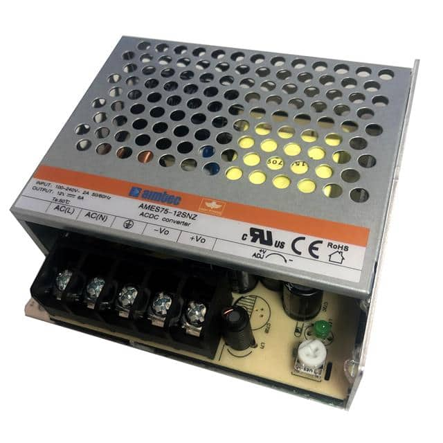
AC/DC 48V 76.8W Datasheet Guide: AMES75-48SNZ-Q Explained
The AMES75-48SNZ-Q from aimtec is a robust AC/DC converter that delivers a nominal 48V output at up to 76.8W of continuous power, making it an ideal choice for industrial control systems, test equipment, and embedded power architectures. Understanding its datasheet thoroughly is critical for reliable system integration. Let us begin with the key electrical specifications. The input voltage range is typically specified as 85 to 264 VAC, with a universal capability that covers both 100V and 240V mains. In practice, this means the converter can operate reliably in regions with unstable grid voltages or during brownout conditions. The output voltage is tightly regulated at 48V, with a typical line and load regulation of ±0.5% and ±1%, respectively. This ensures that downstream loads, such as motors or communication modules, receive a stable supply even when input voltage fluctuates or load current changes. The rated output current is 1.6A, which is the continuous maximum; engineers should note that transient peaks up to 2A for short durations are usually permissible, but prolonged operation beyond 1.6A will trigger overtemperature or overcurrent protection. Efficiency is typically 88% at full load, which is commendable for this power level, and it directly impacts thermal design—lower efficiency means more heat dissipated, so this figure must be cross-referenced with the derating curves.
Absolute maximum ratings are non-negotiable boundaries that, if exceeded, can cause immediate or latent failure. For the AMES75-48SNZ-Q, the absolute maximum input voltage is 305 VAC for no more than 1 second; sustained operation above 264 VAC will damage the input rectifier and capacitors. The output current must never exceed 2.0A, even momentarily, as this can saturate the transformer or degrade the output capacitors. Derating considerations are essential for reliability. The datasheet will provide a derating curve that shows how output power must be reduced as ambient temperature rises above a certain threshold—typically around 50°C for convection-cooled designs. For example, at 70°C ambient, the converter may only be capable of delivering 60% of its rated power. Similarly, input voltage derating applies: at low line (85 VAC), the maximum output power may be reduced to 70W due to increased input ripple current. Engineers must also derate for altitude; above 2000 meters, the air density decreases, reducing cooling efficiency, so output power should be linearly reduced by about 10% per 1000 meters. These derating factors are not optional—they are based on the component's internal temperature rise and the insulation system's limits.
Analyzing the typical application circuit is fundamental to avoiding common pitfalls. The datasheet will show a simplified schematic with input filtering, a bridge rectifier, a switching stage, and output regulation. For the AMES75-48SNZ-Q, the input side requires a fuse—typically a 2A slow-blow type—to protect against short circuits. An input EMI filter, often consisting of a common-mode choke and X/Y capacitors, is recommended to meet conducted emissions standards like EN 55032. The output side may include additional bulk capacitance; the datasheet usually specifies a maximum capacitive load, e.g., 2200 µF, to prevent inrush current from tripping the converter's protection. A key detail is the inclusion of a remote on/off control pin, which allows the converter to be enabled or disabled via a logic signal—useful for power sequencing or low-power standby modes. The output sense lines, if available, compensate for voltage drop in long wires, but this converter likely uses local sensing only. Engineers should also note the isolation voltage: typically 3000 VAC input-to-output, which is crucial for safety in medical or industrial applications where galvanic isolation is mandatory.
The pin configuration and package details dictate mechanical integration. The AMES75-48SNZ-Q is likely a fully encapsulated module with screw terminals or a pin header for board mounting. The pinout should be read carefully: input pins (AC Live, Neutral, and Earth Ground) must be connected with proper wire gauge—at least 18 AWG for the AC lines to handle inrush current. Output pins are marked Vout (+) and Vout (-), and a case ground pin may be present for safety and EMI. The package dimensions are critical for enclosure design; the datasheet will specify a footprint with tolerances. Pay attention to clearance and creepage distances—the minimum spacing between pins and the case should be at least 6.4 mm for 3000V isolation compliance. The converter's weight and mounting holes should be considered for vibration environments; use of standoffs or thermal pads may be required.
Thermal management guidelines are paramount for long-term reliability. The datasheet will provide a thermal impedance figure, typically in °C/W, indicating how much the internal junction temperature rises per watt of dissipated power. For the AMES75-48SNZ-Q, natural convection cooling is assumed, so the converter must have at least 10-15 mm of clearance on all sides for airflow. If mounted inside a sealed enclosure, forced air cooling with a fan may be necessary. The baseplate material—often aluminum—can be attached to a heatsink or chassis using a thermally conductive pad. The maximum case temperature is usually limited to 90°C; exceeding this activates overtemperature shutdown. Engineers should calculate the expected power dissipation: at 76.8W output and 88% efficiency, the converter dissipates about 10.4W. With a thermal resistance of, say, 8°C/W from case to ambient, the case temperature rise above ambient is 83°C, which is unsustainable at 25°C ambient unless a heatsink is used. Therefore, derating or active cooling is mandatory for reliable operation.
Finally, interpreting the timing diagrams and characteristic curves requires a systematic approach. The typical efficiency vs. load curve shows that efficiency peaks at around 80% load and drops at very light loads—below 10% load, efficiency may fall below 70%, which is important for standby power applications. The output ripple and noise curve, often specified at 20 MHz bandwidth, shows peak-to-peak ripple of around 100 mV at full load; this is acceptable for most loads but may require additional post-filtering for sensitive analog circuits. The startup timing diagram illustrates the output voltage rise time, typically 10-20 ms, and the soft-start behavior that limits inrush current. The hold-up time curve shows how long the output remains regulated after input power loss—usually 10-20 ms at full load, which allows for orderly system shutdown. Engineers should also examine the derating curve for input voltage vs. output power, which shows a plateau at high line and a gentle roll-off at low line. By cross-referencing these curves with the absolute ratings and thermal data, one can determine safe operating areas for the specific application environment. Always remember that datasheet curves are typical values; worst-case conditions should be factored in by adding margins—typically 10-20%—to ensure robust design.