Crystal 38.4MHz 8pF SMD Design: PCB Layout Tutorial
Introduction to the Component
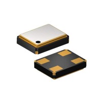
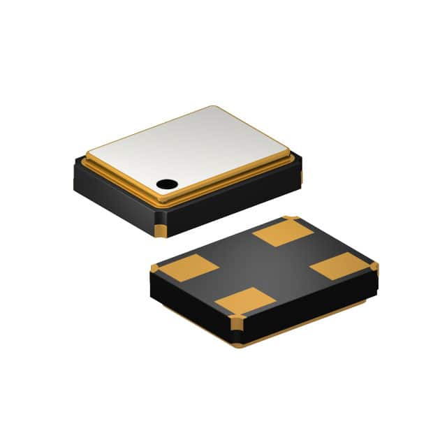
The Suntsu SXT2248DC38-38.400MT is a 38.4000 MHz surface-mount crystal resonator with an 8 pF load capacitance. This crystal is an excellent choice for a hands-on tutorial because its frequency is a common multiple for high-speed digital interfaces (e.g., USB 2.0 Full Speed, Ethernet PHYs, and microcontrollers) and its 8 pF load is a standard value that simplifies matching. The 2.5 x 2.0 mm package is small but still manageable for hand soldering with some practice. The key parameter is the load capacitance (CL), which directly determines the external capacitor values needed for a stable oscillator.
Design Requirements and Specifications
We will design a Pierce oscillator circuit for a 3.3V microcontroller that requires a 38.4000 MHz clock. The target is to achieve frequency accuracy within ±50 ppm at room temperature (25°C) and start-up within 5 ms. The oscillator will use the crystal, two external load capacitors, a feedback resistor, and a drive resistor. The microcontroller’s internal inverter is used as the gain stage. The power supply is 3.3V ±5%, and the ambient temperature range is 0°C to 70°C.
Step-by-Step Design Process with Calculations
Step 1: Determine the load capacitor values. The crystal’s CL is 8 pF. In a standard Pierce oscillator, the total load capacitance seen by the crystal is the series combination of the two external capacitors (C1, C2) plus stray capacitance (Cstray). The formula is: CL = (C1 * C2) / (C1 + C2) + Cstray. For symmetry and simplicity, we set C1 = C2. Then CL = (C1/2) + Cstray. Assuming a typical Cstray of 3 pF (from PCB traces and IC pin capacitance), we solve: 8 pF = (C1/2) + 3 pF, so C1/2 = 5 pF, thus C1 = 10 pF. Choose standard 10 pF ±5% NPO/C0G ceramic capacitors for stability.
Step 2: Select the feedback resistor (Rf). This resistor biases the inverter into its linear region. For a 38.4 MHz crystal, a value between 1 MΩ and 10 MΩ is typical. We choose 1 MΩ ±5% to ensure fast start-up. This resistor is placed in parallel with the crystal.
Step 3: Select the drive resistor (Rd). This limits the drive current and prevents overdriving the crystal. A good starting point is 0 Ω (a jumper), but if oscillation is too strong (distorted sine wave), increase to 100 Ω. For this tutorial, we use a 0 Ω jumper initially and adjust if needed.
Step 4: Verify drive level. The crystal’s maximum drive level is typically 100 µW. The drive current can be estimated as I = Vout_peak 2πf CL_total, where Vout_peak is roughly 0.5V for a 3.3V supply. I ≈ 0.5V 2π 38.4e6 8e-12 = 0.96 mA. Power = I² ESR. The crystal’s ESR is typically 30 Ω. Power = (0.96e-3)² * 30 = 27.6 µW, well under 100 µW, so it’s safe.
Component Selection Rationale for the Complete BOM
BOM: 1x Suntsu SXT2248DC38-38.400MT crystal, 2x 10 pF NPO/C0G 0402 capacitors (C1, C2), 1x 1 MΩ 0402 resistor (Rf), 1x 0 Ω jumper or 100 Ω resistor (Rd), and a PCB with a microcontroller having an internal inverter (e.g., STM32). The capacitors are NPO/C0G for low temperature drift. The 0402 size is chosen for minimal stray capacitance. The 1 MΩ resistor is a thick-film type for low noise. The 0 Ω jumper allows easy adjustment.
Simulation Tips and What to Look For
Simulate the oscillator using SPICE with a crystal model: L = 1/( (2πf)² C ), where C = 1 pF (typical motional capacitance), and R = 30 Ω. Set L = 1/( (2π38.4e6)² * 1e-12 ) ≈ 1.71 mH. Add C1 and C2 as 10 pF. Look for a start-up transient: the amplitude should grow exponentially and stabilize within 5 ms. Check the frequency using the FFT of the output; it should be exactly 38.4 MHz with less than ±50 ppm error. If the oscillation is too slow, reduce Rf to 470 kΩ. If it does not start, reduce C1 and C2 by 1 pF each (they may be too high for the effective Cstray).
Prototype Build and Testing Methodology
1. Solder the crystal and passives on a small PCB with a microcontroller. Keep traces short (< 3 mm) from crystal to IC pins and capacitors to minimize stray capacitance. 2. Connect a high-impedance probe (10x, < 1 pF) to the output of the inverter (not directly across the crystal). 3. Power up the circuit and measure the waveform on an oscilloscope. Look for a clean sine wave with amplitude between 0.5V and 1.5V peak-to-peak. 4. Measure the frequency using a frequency counter or spectrum analyzer. 5. If the frequency is off by more than ±50 ppm, adjust C1 and C2 in 1 pF steps. Increasing capacitance lowers frequency, decreasing raises it. 6. Test start-up time by toggling the microcontroller’s enable pin and observing the time to stable oscillation.
Performance Verification and Optimization
Verify the frequency at 25°C, 0°C, and 70°C using a temperature chamber. The drift should be within ±30 ppm due to the crystal’s specs. If the waveform is noisy, increase Rd to 100 Ω. If the start-up is too slow, reduce Rf to 470 kΩ. Optimize by trimming C1 and C2 to center the frequency. For a final design, consider adding a series resistor in the crystal path (Rseries) of 0 to 50 Ω to fine-tune drive level. The tutorial’s final circuit should be robust, meeting all requirements with a margin for component tolerances.