Mastering the 15m LC/UPC ST/UPC OM2 Datasheet: A Guide
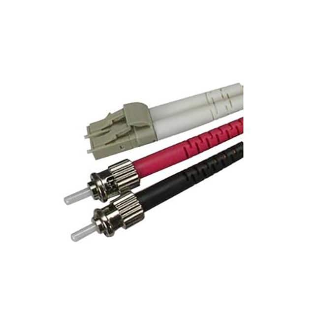
This component is a fiber optic patch cable, specifically a 15-meter LC/UPC to ST/UPC OM2 Multimode cable from Coolgear, SKU CM-102948-L2BSTK. As a passive optical interconnect, it does not have traditional electrical specifications like voltage or current ratings. Instead, its performance is defined by optical and mechanical parameters that are critical for signal integrity in high-speed data transmission. The key specifications to interpret include the fiber type (OM2), connector types (LC/UPC and ST/UPC), and length (15 meters). OM2 multimode fiber has a core diameter of 50 micrometers, which supports modal bandwidth of 500 MHz·km at 850 nm and 500 MHz·km at 1300 nm. In practice, this means the cable is suitable for short-to-medium distance links up to 550 meters at 1 Gbps (1000BASE-SX) and up to 150 meters at 10 Gbps (10GBASE-SR). The 15-meter length is well within these limits, ensuring low signal dispersion and reliable operation for data center, LAN, or telecom applications. The LC/UPC and ST/UPC connectors feature an Ultra Physical Contact (UPC) polish, which provides a typical return loss of -50 dB or better, minimizing back reflections that can degrade laser performance in transceivers. This is especially important for high-speed or analog signal transmission where reflection-induced noise must be avoided.
Since this is a passive component, absolute maximum ratings do not apply in the conventional sense, but there are derating considerations for mechanical and environmental stress. The cable should not be bent beyond its minimum bend radius, typically 30 mm for OM2 fiber under load and 15 mm for long-term static installation. Exceeding this can cause micro-bending losses, which increase attenuation permanently. The operating temperature range for standard patch cables is usually -20°C to +70°C, but derating is required near the extremes: at high temperatures, the buffer material may soften, increasing signal loss; at low temperatures, the jacket can become brittle. For this Coolgear cable, which uses a PVC or LSZH jacket (check datasheet), avoid tensile loads beyond 50 N during installation to prevent fiber strain. For permanent installations, derate tensile load to less than 10 N. The connector insertion loss should be below 0.3 dB per mated pair, but repeated mating cycles (typically 500-1000 cycles) will gradually increase loss due to wear; derate performance after 200 cycles for critical links.
For a typical application circuit analysis, think of this cable as part of a fiber optic link between a transceiver (e.g., SFP module) and a receiver. The circuit is purely optical: the transmitter's laser or LED launches light into the LC/UPC connector, which couples into the 50/125 µm OM2 fiber core. The signal propagates through the 15-meter length, experiencing attenuation (typically ≤3.0 dB/km at 850 nm, so ≤0.045 dB for this cable) and modal dispersion. The ST/UPC connector mates with the receiver. No electrical circuit exists, but the link budget must account for connector losses (0.3 dB per pair), fiber attenuation, and splice losses if any. For a 10 Gbps link, ensure the total loss is less than the power budget of the transceiver (often 2-6 dB). For example, using a 10GBASE-SR SFP+ with -7.3 dBm receiver sensitivity and +1 dBm launch power, the total system loss must be under 8.3 dB. This cable contributes about 0.6 dB (two connectors + fiber loss), leaving ample margin. Designers should also consider the modal bandwidth: at 10 Gbps, OM2 fiber supports up to 150 meters, so 15 meters is safe. If using higher data rates like 25 Gbps, OM2 may be marginal; OM3 or OM4 would be preferred.
The pin configuration for this component is non-electrical; it refers to the connector mechanical interface. The LC connector has a 1.25 mm ferrule with a push-pull latching mechanism, and the ST connector has a 2.5 mm ferrule with a bayonet twist-lock. The UPC polish is visible as a convex dome on the ferrule end-face. Package considerations are about the cable jacket: this is typically a 2.0 mm or 3.0 mm diameter tight-buffered cable, reinforced with Kevlar or aramid yarn for pull strength. For installation in cable trays or patch panels, ensure the bend radius is maintained. The connectors are compact—LC is ideal for high-density panels, while ST is more robust for lab or industrial environments. The duplex configuration (likely two fibers in a zip-cord) requires careful polarity management: ensure the Tx of one device connects to the Rx of the other using a crossover or straight-through cable, depending on the transceiver.
Thermal management is minimal for passive fiber, but the cable jacket material has a maximum operating temperature. For PVC jackets, use below 70°C; for LSZH (low-smoke zero-halogen), it can be up to 85°C. In high-density racks, ensure the cable is not routed near hot exhaust air from servers or power supplies, as this can degrade the jacket over time and increase attenuation. Do not zip-tie cables too tightly; use Velcro straps to avoid crimping the fiber and inducing loss. For outdoor or industrial environments, consider armored variants if mechanical protection is needed.
To interpret timing diagrams or characteristic curves, first note that fiber optic cables have no electrical timing; instead, look for optical waveforms. The datasheet may include a graph of attenuation vs. wavelength, showing a typical loss of ~2.5-3.0 dB/km at 850 nm and 0.5-1.0 dB/km at 1300 nm. A bending loss curve shows how attenuation increases with decreasing bend radius; for example, at a 30 mm radius, loss may increase by 0.1 dB, but at 15 mm, it could spike to 1 dB. The modal dispersion chart, sometimes called the "overfill" condition, shows the pulse broadening due to different path lengths in the core. For OM2 fiber, the differential mode delay (DMD) is specified at 850 nm to ensure 10 Gbps performance. The eye diagram from a transceiver test might be included—an open eye indicates low jitter and sufficient signal-to-noise ratio. When reading these curves, look for the worst-case values: maximum attenuation over the full temperature range and minimum bend radius for long-term reliability. Any sudden slope changes in the loss vs. wavelength plot indicate absorption peaks from impurities; OM2 fiber should have no such peaks in the 800-1350 nm range. Finally, the datasheet may include a connector return loss histogram showing typical performance of -50 dB. For a 15-meter cable, these curves confirm that the link margin is generous for standard applications, but always verify against your transceiver's specifications to avoid link errors.