Mastering 20-Pin Header Troubleshooting: HTSW-120 Fixes
Typical Failure Modes and Root Causes
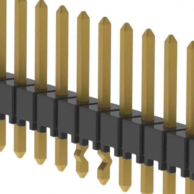
The HTSW-120-07-G-S-LL is a 20-position, 2.54mm pitch, vertical through-hole header with a locking latch (LL). In my field experience, failures rarely originate from the header itself but from how it is integrated. The most common failure mode is intermittent contact—a connection that works when pressed or wiggled but fails in operation. This is almost always caused by insufficient solder fillet on the tail side, leading to a cold joint that fractures under vibration. The second most common issue is pin bending, especially if the header is inserted into a mating connector at an angle. The “LL” locking latch is a frequent culprit: if the latch is over-stressed during mating, it can crack, causing the mating connector to partially disengage. Less common but more severe is solder wicking up the pin during wave soldering, which can reduce the effective spring contact length inside the mating receptacle, leading to high resistance over time. Finally, flux residue trapped under the header body can cause dendritic growth and shorts, particularly in high-humidity environments.
Step-by-Step Debugging Methodology
When a board with this header fails, follow a systematic approach. First, perform a visual inspection under a 10x loupe: look for lifted pads, cracked solder joints, bent pins, or debris between pins. Next, use a multimeter in continuity mode to check each pin from the solder tail to the mating side—do this with the mating connector unplugged. If continuity is good, proceed to dynamic testing: apply a slight lateral force to the header while measuring resistance across a daisy-chained pair of pins. Any resistance spike above 0.5 ohms indicates a mechanical issue. If all pins pass, move to signal integrity testing with an oscilloscope—probe the header pin and the destination IC pad simultaneously to compare waveforms. Look for excessive ringing or attenuation that suggests a high-resistance connection. Finally, if the header is in a high-vibration environment, perform a tap test: lightly tap the header with a plastic probe while monitoring the circuit output. This will reveal intermittent faults that static tests miss.
Common Mistakes in Schematic Design and PCB Layout
The most frequent schematic error is misassigning pin numbers—the HTSW-120 has 20 pins, but if you mirror the footprint, pin 1 becomes pin 20, causing a complete reversal of signals. Always cross-reference the datasheet’s pinout with your symbol. In layout, the classic mistake is using a 0.025” square pad for a 0.025” square pin. The datasheet recommends a 0.040” drilled hole with a 0.070” pad for reliable soldering. If you use a smaller pad, you risk annular ring breakout. Another critical error is placing the header too close to tall components, such as electrolytic capacitors, which physically obstructs the mating connector’s latch. Also, ensure the keep-out zone for the locking latch is respected—the latch extends beyond the body, and many designers forget to leave a clearance on the top side. Finally, for high-speed signals, do not route traces under the header’s GND pins unless you’ve accounted for the capacitance change—this is a common cause of impedance discontinuities.
Verifying Component Authenticity and Quality
Given Samtec’s reputation, counterfeit parts are rare but possible. First, check the laser marking: genuine Samtec headers have a clean, high-contrast “HTSW-120-07-G-S-LL” marking on the side. Counterfeits often have a blurry or misaligned print. Second, measure the pin dimensions with a caliper: the pins should be 0.025” square and protrude 3.05mm from the body. Third, test the latch action—the LL latch should have a crisp, audible click when fully engaged. If the latch feels mushy or requires excessive force, it’s likely a knock-off. Also, verify the plastic material: genuine parts use high-temp black LCP that does not discolor when touched with a soldering iron. A fake may melt or smell like cheap ABS. Finally, check the lead-free finish: the “G” in the part number indicates gold plating on the contact area. A genuine part will have a bright, uniform gold finish; dull or patchy gold indicates a re-plated or inferior product.
Measurement Techniques and Test Equipment
For basic continuity, a 4-wire milliohm meter is essential—a standard DMM will show 0.1 ohms but miss a 0.5-ohm joint. Use a Kelvin probe on the solder tail and the mating pin to measure contact resistance; a new header should read under 10 milliohms per pin. For signal integrity, use a 100MHz+ oscilloscope with a 1x passive probe—do not use 10x probes for low-level logic. When probing, attach a spring ground lead directly to the header’s GND pin to avoid ground bounce. For thermal stress testing, use a thermal cycling chamber (-40°C to +85°C) and monitor resistance continuously with a data logger. For high-vibration environments, a piezoelectric accelerometer mounted near the header can correlate mechanical stress with electrical failure events. Finally, always use a solder wick to remove the header if you suspect a pad issue—do not force it out, as you’ll damage the plated through-hole.
When to Suspect the Component vs. the Surrounding Circuit
As a rule of thumb, suspect the header first if the failure is mechanical—loose connection, bent pins, or latch breakage. Suspect the circuit if the failure is electrical but the header passes all continuity and resistance tests. A key diagnostic: if pin 1 and pin 20 have identical symptoms, the issue is likely in the header’s common bus (e.g., a cracked solder joint on a shared GND pin). If only one pin fails, check the trace and the IC connected to that pin. Also, check the mating connector—often the problem is the female socket losing its spring tension, not the male header. In one case, a customer reported intermittent failure on 5 pins out of 20. The header was fine; the mating connector had been over-mated and its contacts had relaxed. Replacements of the mating connector solved the issue. Conversely, if the header’s pins show discoloration (blue/purple oxide), that indicates overheating from excessive current—that’s a circuit design problem, not a header defect.
Real-World Case Studies
Case 1: Cold Solder Joint in an Automotive ECU. A customer had intermittent engine misfires. The HTSW-120 header connecting the ECU to the wiring harness failed under vibration. The root cause was a wave solder process with insufficient preheat, causing incomplete wetting on one tail. The fix was to reflow the joint manually; all other pins were fine. Lesson: always inspect solder fillets for a concave, shiny appearance.
Case 2: Latch Breakage in a Medical Device. A device failed when the locking latch snapped off during repeated insertion cycles. The header was genuine, but the PCB had a sharp edge that caught the latch. The solution was to add a 0.5mm standoff to the mounting hole. Lesson: mechanical clearance is as important as electrical.
Case 3: Pin 1 Reversal in a Prototype. A developer had a board where all signals were reversed. The schematic symbol had pin 1 on the left, but the PCB footprint had pin 1 on the right. The fix was to rotate the footprint 180°. Lesson: always print a 1:1 scale layout and physically compare with the actual header before production.