Troubleshooting the BD49K41G-TL: Voltage Supervisor Guide
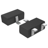
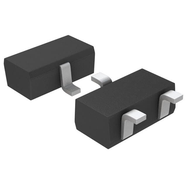
The BD49K41G-TL from Rohm Semiconductor is a voltage detector, or supervisor, IC designed to monitor a supply rail and assert a reset signal when that voltage falls below a precise threshold. While these devices are inherently robust, they are often the silent culprits in system failures, primarily because their function is passive until something goes wrong. This guide focuses on practical, field-tested methods for debugging circuits using this specific 3-pin SSOP part (which is functionally a reset generator with an open-drain output).
Typical Failure Modes and Root Causes
The most common failure is spurious resets—the system randomly resets or hangs without obvious cause. Root causes usually fall into three categories: (1) transient voltage dips on the monitored rail that are faster than the IC’s internal delay (the BD49K41G has a fixed delay, typically 200ms, but a fast glitch can still trip the comparator if it exceeds the hysteresis band); (2) excessive noise coupling into the sense pin (VDD pin) via a poorly decoupled supply; and (3) incorrect threshold selection—the BD49K41G has a 4.1V detect threshold, but if your actual rail is 3.3V or 5V with 10% tolerance, you may be operating too close to the edge. Another failure mode is no reset output at all, where the output stays high or floating. This is almost always due to an open-drain output not being pulled up, or the pull-up resistor being tied to a rail that is itself dead during a brownout. Finally, permanent damage (output stuck low) often results from exceeding the absolute maximum rating on VDD (typically 6.5V) or applying reverse polarity.
Step-by-Step Debugging Methodology
Start with the power supply, not the IC. First, measure the actual voltage at the BD49K41G’s VDD pin (pin 1) with a digital storage oscilloscope (DSO) using a 10x probe, not a multimeter. Set the scope to AC coupling, 10mV/div, and 1µs/div to look for ripple or glitches. If you see a dip below 4.1V – even for 10µs – you have found the root cause. Second, verify the pull-up resistor on the output (pin 3). It should be between 10kΩ and 100kΩ, connected to the same rail as the microcontroller’s VDD. If it’s tied to a 5V rail while the MCU runs at 3.3V, the reset pin will be overvolted. Third, check the ground connection (pin 2). The BD49K41G uses a single ground; ensure it is a dedicated trace back to the common ground point, not daisy-chained through a high-current path. Finally, measure the output waveform during a power-up/down cycle. The output should go low when VDD crosses 4.1V and stay low until VDD rises above 4.1V plus hysteresis (about 100mV). If the output is low at power-up but never goes high, check the pull-up or the MCU’s reset pin configuration.
Common Mistakes in Schematic and PCB Layout
The most frequent schematic error is forgetting the pull-up resistor on the open-drain output. The datasheet is clear, but many designers incorrectly assume the output is push-pull. On the PCB, the biggest issue is placing the decoupling capacitor (0.1µF) too far from the VDD pin. The trace inductance between the cap and the IC can cause a 200mV drop during a load step, tripping the supervisor. Keep the cap within 2mm of the pin. Another classic mistake is running the reset trace parallel to a high-speed clock or PWM line for more than 5mm. This induces crosstalk, causing false resets. Use a ground guard trace or move the trace to another layer. Also, avoid using vias to route the sense line—the inductance can make the threshold unstable. Finally, if the BD49K41G is monitoring a 3.3V rail, double-check that you have the correct SKU; the “41” means 4.1V, so using it on a 3.3V rail will cause a permanent reset condition.
Verifying Component Authenticity and Quality
Counterfeit supervisors are a real problem, especially in the 3-pin SOT-23 package. First, inspect the top marking. Rohm uses a specific laser-marked code (e.g., “BD49K41G” or a shortened alphanumeric). Compare it with the datasheet’s marking diagram. Second, measure the quiescent current (Icc). A genuine BD49K41G draws about 1µA at 5V. If you measure >10µA, it’s likely a fake or a different voltage variant. Third, test the threshold precisely. Use a programmable DC power supply and slowly ramp VDD down at 10mV/s while monitoring the output with a logic analyzer. The threshold should be 4.1V ±1.5% (about 61.5mV). If it triggers at 3.8V or 4.5V, the part is either counterfeit or damaged. Also, check the hysteresis—it should be about 100mV. A cheap multimeter cannot verify this; you need an oscilloscope in DC mode with a slow sweep.
Measurement Techniques and Test Equipment
For this IC, your essential tools are: a DSO with at least 100MHz bandwidth (to catch fast glitches), a low-ESR probe (use a spring tip, not the long ground lead), a precision source measure unit (SMU) or a lab supply with fine voltage control, and a logic analyzer to capture reset timing relative to the MCU clock. When measuring, never use a 1x probe—it loads the high-impedance sense node and will show false dips. Instead, use a 10x probe and set the scope to 20MHz bandwidth limit to filter noise. For transient testing, inject a 100mV step on VDD using a function generator through a 1kΩ resistor. This simulates a load transient. Watch the output—it should not assert reset for steps shorter than the internal delay.
When to Suspect the Component vs. the Surrounding Circuit
Suspect the IC itself only after you have verified: (1) VDD is clean and within 4.1V ±5% with no dips; (2) the pull-up resistor is correct and connected to the right rail; (3) the ground is solid; and (4) the PCB layout is clean. If all those pass, then test the IC in isolation. Remove it from the board (or lift the output pin) and wire it on a breadboard with a fresh 0.1µF cap and a 10kΩ pull-up to 5V. Slowly ramp VDD. If it behaves correctly off-board, the problem is your layout. If it fails off-board, you have a bad part—replace it with a known-good unit, not one from the same reel. A common trap is blaming the supervisor when the real issue is an MCU that has its brown-out detection (BOD) set to a higher threshold than 4.1V, causing the MCU to reset before the supervisor can.
Real-World Case Studies
Case 1: Intermittent resets in a motor controller. The BD49K41G monitored a 5V rail. The output was low, but the MCU resets were random. Debugging revealed a 300mV dip on VDD every time the motor stalled. The decoupling cap was 10mm away. Moving the cap to within 1mm of the pin and adding a 10µF bulk capacitor solved it.
Case 2: System stuck in reset. The output was permanently low. The pull-up was tied to a 3.3V rail that was derived from the 5V rail after a regulator. During a brownout, the 3.3V rail collapsed before the supervisor’s output could go high. Solution: tie the pull-up to the same 5V rail that the supervisor monitors.
Case 3: False positives on a battery-powered device. A customer reported that the device shut down at 4.05V, not 4.1V. Analysis showed that the battery’s internal resistance caused a 60mV drop under load, and the IC’s threshold was 4.1V minus 50mV hysteresis. They chose the 4.0V variant (BD49K40G)