Sylvania EXE/240 Replacement: Application Note Guide
Recommended circuit topologies and design best practices
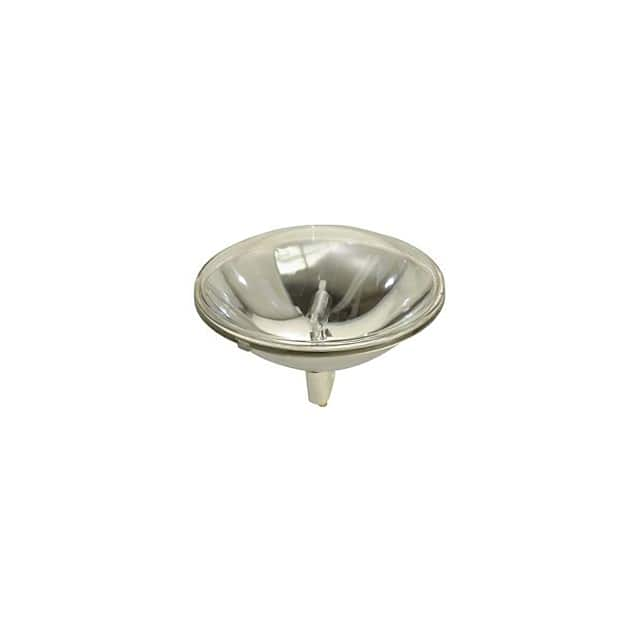
The Interlight WW-5BUC-4 is specified as a direct replacement for the Sylvania EXE/240, which is a halogen infrared (IR) lamp commonly used in reflow ovens, drying systems, and industrial heating processes. Unlike LED replacements, this is a resistive, filament-based load that operates on a 240V AC supply. The most reliable topology is a simple, directly heated resistive circuit with a series-connected thermal cutoff or solid-state relay (SSR) for on/off control. Do not attempt to drive this lamp with PWM or phase-cut dimming unless the lamp’s datasheet explicitly allows it—halogen filaments have low thermal mass and can experience accelerated failure from rapid thermal cycling. For temperature-controlled systems, use a closed-loop topology with a thermocouple or IR sensor feeding a PID controller that drives an SSR with zero-cross switching. This minimizes inrush current and extends filament life. If multiple lamps are used in parallel, each must have its own independent fuse or circuit breaker, as the filament’s cold resistance is roughly 10–15% of its hot resistance, causing a significant inrush spike at turn-on.
Component selection guidelines for supporting passives
The primary supporting passive is the inrush current limiter. A negative temperature coefficient (NTC) thermistor rated for at least 5A steady-state and 240VAC should be placed in series with the lamp. Select an NTC with a cold resistance of 20–50 ohms to limit the initial surge to under 10A; after 1–2 seconds, the NTC heats up and its resistance drops to under 1 ohm, minimizing power loss. For the SSR, choose a device rated at 25A or higher (to handle a 10x inrush) with a blocking voltage of at least 600V. Use a snubber network—a 47nF, 630V film capacitor in series with a 100-ohm, 2W resistor—across the SSR’s output terminals to suppress inductive transients from wiring. For EMI filtering, a line filter with a common-mode choke (e.g., 10mH) and X/Y capacitors (0.1µF X2, 2200pF Y2) is essential. The fuse should be a slow-blow type rated at 2A for a single 240W lamp, but if you are paralleling multiple lamps, size the fuse at 125% of the total steady-state current.
PCB layout recommendations and routing tips
Given the high voltage and heat, do not place the lamp socket directly on the PCB. Instead, use a separate terminal block or high-temperature ceramic connector, and keep the PCB at least 10mm away from the lamp’s radiant heat zone. On the PCB, route the live and neutral traces with a minimum 3mm creepage distance and 2mm clearance for 240VAC, per IPC-2221. Use a 2-ounce copper weight for all power traces to reduce resistance and heat build-up. Place the NTC thermistor as close to the lamp’s terminal as possible, but with a 5mm air gap to avoid thermal coupling that would cause the NTC to heat up prematurely. The SSR should be mounted on a heatsink, and its control input traces should be kept at least 5mm away from the high-voltage traces to prevent noise coupling. For the snubber network, place the resistor and capacitor physically adjacent to the SSR terminals—do not route long wires to them, as that adds parasitic inductance. Always use a ground plane on the bottom layer, but cut a slot under the high-voltage traces to prevent capacitive coupling to the ground plane.
EMC/EMI considerations and mitigation strategies
The main EMI source is the inrush current and the abrupt current cutoff when the SSR switches off. Because the lamp is a pure resistive load, there is no arc or spark, but the high di/dt during turn-off can cause ringing with the wiring inductance. The snubber network described above is your first line of defense. Additionally, place a ferrite bead (e.g., 100MHz, 100Ω) on each AC line right at the PCB entry point. For conducted emissions, the line filter must be placed between the AC input and the SSR, not after the SSR, to filter both the lamp current and any noise generated by the controller. For radiated emissions, keep the loop area of the high-voltage traces as small as possible—route the phase and neutral traces close together (but with proper spacing) to cancel magnetic fields. If the lamp is in a metal enclosure, ground the enclosure to the earth terminal of the filter. Also, use a 1MΩ bleeder resistor across the lamp’s terminals (rated for 240VAC) to discharge any residual voltage when the SSR is off, preventing nuisance ESD discharges.
Common design pitfalls and how to avoid them
The most frequent mistake is undersizing the SSR or fuse based on the lamp’s rated power (240W) without accounting for the inrush current. Always measure the cold resistance of the lamp (typically 20–30 ohms) and calculate the initial surge: at 240VAC, that can be 8–12A for a few milliseconds. Another pitfall is placing the NTC thermistor too close to the lamp’s radiant heat, causing it to heat up before current flows, which defeats its purpose. Conversely, placing it too far away adds series resistance that reduces heating efficiency. Do not use a standard triac dimmer for this lamp—halogen filaments are designed for constant voltage, and phase-cut control will cause flicker and premature burnout. Also, avoid using a relay for switching; relays have contact bounce and arcing that will erode contacts quickly at 240VAC. Finally, never run the lamp at voltages above 250VAC, as this will drastically shorten filament life—use a voltage stabilizer if your mains is unreliable.
Prototyping tips and bench testing procedures
Start with a bench setup using a variable AC transformer (Variac) to slowly ramp up the voltage from 0V to 240V over 5 seconds while monitoring the current with a clamp meter. Verify that the inrush current does not exceed the SSR’s rated peak. Use a thermocouple attached to the lamp’s glass envelope to confirm the surface temperature stays within the recommended range (typically 300–400°C for IR lamps). For the NTC, measure its resistance before and after power-up to ensure it drops below 1 ohm within 2 seconds. When testing the EMI filter, use a spectrum analyzer with a line impedance stabilization network (LISN) to verify conducted emissions stay below EN 55011 Class A limits. Also, perform a thermal soak test: run the lamp at full power for 2 hours, then measure the temperature rise on the PCB near the SSR and NTC—if it exceeds 85°C, add more copper area or a small fan. Finally, test the snubber by turning the SSR off at 90° and 270° phase angles (using a zero-cross SSR, this is automatic) and observe the voltage waveform with a differential probe to ensure no ringing exceeds 600V. Always wear safety glasses and use a fused isolation transformer during bench testing, as 240VAC is lethal.