Mastering PIM433 EPD: Inky What Tri-Color Display Guide
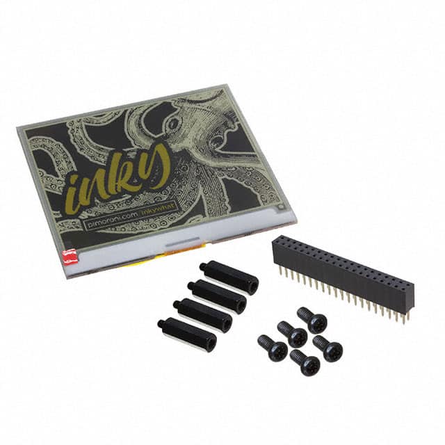
The INKY WHAT Yellow/Black/White EPD (PIM433) is a 4.0-inch tri-color e-paper display designed for low-power, high-visibility applications such as shelf labels, status boards, and IoT dashboards. Unlike standard TFTs, this display requires a specific drive sequence and voltage rail management. The most critical design decision is the interface topology. The board integrates a Pico-Style connector (20-pin, 2.54mm pitch) that breaks out the SPI bus, plus dedicated control lines: BUSY, RESET, DC, CS, and CLK. For reliable operation, you must implement a 3.3V logic level system. Do not attempt to drive the panel with 5V logic; the onboard controller (IL0398) is not 5V tolerant. Use a microcontroller (MCU) with 3.3V I/O, or add a level shifter (e.g., TXB0108) if your host is 5V. The panel’s power supply is derived from the host’s 3.3V rail, but the EPD’s internal boost converter generates the high voltages (typically ±15V and +22V) needed for the electrophoretic ink. Therefore, your 3.3V rail must be clean and capable of supplying at least 250mA peak current during refresh cycles. A low-dropout regulator (LDO) with a fast transient response, such as the AP2112K-3.3, is recommended. Avoid using a switching regulator directly without a post-filter LC stage, as ripple on the input voltage can cause ghosting or incomplete updates.
For supporting passives, place a 10µF X5R ceramic capacitor (0805 or larger) as close as possible to the PIM433’s 3.3V input pin. Additionally, add a 0.1µF decoupling capacitor directly at the connector. The EPD board itself has onboard charge pump capacitors, but you must not rely on those for your host-side filtering. For the SPI lines, series resistors (33Ω to 47Ω) are recommended to damp ringing and reduce EMI. These resistors should be placed near the MCU’s SPI pins. For the BUSY line, add a 10kΩ pull-up to 3.3V; the EPD’s BUSY output is open-drain. If you are using a shared SPI bus with other peripherals, ensure that the EPD’s CS line is actively pulled high when not selected (do not rely on the MCU’s default high-impedance state). Also, do not share the SPI bus with high-speed devices (e.g., SD cards) without careful bus arbitration, as the EPD is sensitive to timing glitches during refresh.
PCB layout is straightforward but requires discipline. Keep the ribbon cable or FFC connection to the EPD as short as possible—under 10cm is ideal. Longer cables increase parasitic capacitance and can cause the clock signal to distort, leading to display corruption. Route SPI traces as a group with a ground return adjacent to the CLK line. Use a solid ground plane on your PCB, and avoid splitting it under the connector. The EPD’s flexible PCB has a gold-fingered edge; ensure your connector is a low-insertion-force type (e.g., a 20-pin 0.5mm FPC or a standard female header). Do not solder the EPD directly to your board; use a socket that allows easy removal for prototyping. For the high-voltage boost converter inside the EPD, there are no external components, but you must ensure your PCB’s ground plane does not run directly underneath the EPD’s driver IC area, as that can couple noise into the panel. Instead, keep a 5mm keep-out zone on the top layer under the EPD module.
For EMC/EMI, the primary concern is the EPD’s internal DC-DC converter. During refresh, it operates at a switching frequency around 1MHz and can radiate harmonics. To mitigate, add a ferrite bead (e.g., 600Ω at 100MHz) in series with the 3.3V input line, placed before the 10µF capacitor. This forms a low-pass filter. For the SPI lines, keep the loop area small by routing CLK and MOSI close to each other—do not run them on opposite sides of the PCB. If your product must pass radiated emissions tests, consider adding a common-mode choke on the SPI lines, though a series resistor is often sufficient for short traces. Also, the EPD’s BUSY line can toggle rapidly; add a 1nF capacitor to ground on this line to filter noise, but ensure it does not slow the signal below the MCU’s threshold (the EPD is slow, so this is safe). Avoid routing the SPI bus near the EPD’s high-voltage area (the top edge of the panel) as that is where the boost converter’s inductor is located.
Common pitfalls include attempting to refresh the display too frequently. The tri-color ink requires a specific waveform sequence; the EPD has a busy-wait mechanism. If you ignore the BUSY line and send a new command while the panel is updating, you will permanently damage the ink’s calibration, causing ghosting. Always check BUSY before writing to the display. Another pitfall is powering down the 3.3V rail while the EPD is in the middle of a refresh. The panel’s internal charge pump needs to discharge properly; abruptly cutting power can leave residual charge, leading to a “burned-in” image. Implement a power-down sequence: wait for BUSY to go low, then issue a deep-sleep command (0x10), and only then remove power. Also, do not use the EPD’s VCC pin to power other peripherals; it is not a regulated output. A frequent mistake is using a 3.3V MCU that has weak drive strength; the SPI clock must have a rise time under 200ns. If using a Raspberry Pi Pico, set the SPI clock to 4MHz or less—higher speeds are unnecessary and can cause reflections.
For prototyping, use a Pico or any 3.3V MCU with the Pimoroni’s provided Python or C++ libraries. First, bench-test with a separate 3.3V bench supply set to 3.3V and current-limited to 300mA. This protects against short circuits. Connect the SPI lines, then power the EPD. Run a simple “clear screen” test. If the display shows noise or partial pixels, immediately check the 3.3V rail with an oscilloscope—look for droop during refresh. Use a logic analyzer to verify that the MOSI and CLK signals have no ringing. When testing, always use a fresh EPD; if you have previously driven it with incorrect voltages, the panel may be permanently damaged. Also, be aware that the yellow color is not as fast as black/white; expect a refresh time of 12-15 seconds. During bench testing, keep the EPD away from strong magnetic fields (e.g., large transformers) as they can disturb the electrophoretic particles. Finally, document the exact power sequence: apply 3.3V, wait 10ms, reset the EPD (RESET pin low for 10ms), wait 50ms, then issue commands. This reliable sequence will prevent most early failures.