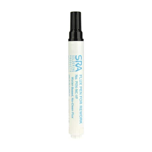
SRA 312-VF Datasheet Guide: VOC-Free Water-Based Pen-NC-VF
The SRA 312-VF, marketed under the SKU PEN-NC-VF, is a critical anomaly in the world of electronic components: it is not a silicon-based device, but rather a chemically engineered consumable—specifically, a VOC-free, water-based no-clean flux pen. For the design engineer, interpreting its "datasheet" requires a paradigm shift from electrical parameters to chemical and mechanical performance metrics. Understanding this document is essential for ensuring solder joint reliability, preventing ionic contamination, and maintaining process compliance in rework and prototyping environments.
The key "electrical" specifications for the SRA 312-VF are not voltage or current ratings, but rather insulation resistance and electromigration resistance. The datasheet typically cites a surface insulation resistance (SIR) value, often exceeding 1 x 10^11 ohms after a standard 85°C/85% relative humidity test. In practice, this figure dictates the maximum allowable residue left on the board. A high SIR ensures that the flux's non-conductive residue will not create parasitic leakage paths between closely spaced conductive traces, which is paramount for high-impedance analog circuits or high-speed digital lines where even picoamp leakage can cause jitter or offset errors. The "water-based" designation is crucial here; it signifies a formulation free of isopropyl alcohol (IPA) and other volatile organic compounds, which directly addresses environmental regulations like the Clean Air Act while eliminating the fire hazard associated with solvent-based fluxes. The "no-clean" designation, however, is more nuanced. It does not mean zero residue, but that the residue is benign enough to be left on the board for most applications, provided the SIR and electromigration thresholds are not exceeded. In practice, this means the engineer must still weigh the risk of residue-induced leakage against the cost and time of a cleaning step.
Regarding absolute maximum ratings and derating, the thermal profile is the primary constraint. The datasheet specifies a maximum activation temperature, typically around 350°C (662°F), which corresponds to the tip temperature of a soldering iron. Exceeding this temperature does not destroy the pen, but it thermally decomposes the activator chemistry, producing carbonized, resinous char that is difficult to remove and can become hygroscopic, absorbing moisture and lowering SIR over time. Derating here means operating at the lowest temperature that achieves a proper fillet, typically 300-320°C, to preserve the flux's activity gradient. Additionally, the pen has a shelf life, often 12 months from date of manufacture, and a storage temperature rating (usually 15-25°C). Storing it outside this range, particularly in high heat, accelerates solvent evaporation, thickening the flux and altering its viscosity, which directly impacts its ability to wick into a via or under a lead. The "VF" (VOC-Free) designation also carries an implicit derating for cleaning compatibility; you cannot use standard alcohol-based cleaners on the residue, as they may not dissolve the water-based salts.
There is no pin configuration, but there is a mechanical delivery system that demands analysis. The pen consists of a reservoir barrel, a porous felt applicator tip, and a cap. The applicator tip acts as the "output pin." The datasheet or user guide will specify the flow rate, which is a function of the felt's porosity and the flux's viscosity. In practice, this translates to how many square inches of board area a single pen can cover, often cited as 10-15 linear feet of solder joints. The package consideration is the pen's ergonomics and precision. The tip must be able to reach into tight SMD pads without wicking excess flux onto adjacent components. A critical interpretation is that the tip is not a solder applicator; it is a flux applicator. Applying the flux to the pad, preheating the board, and then introducing solder is the correct sequence. The datasheet will also caution against touching the tip to the soldering iron, as this will melt the felt and contaminate the flux with plastic residue.
Thermal management guidelines are counterintuitive for a flux. The goal is not to dissipate heat, but to manage the thermal gradient for optimal activation. The flux is designed to become active at approximately 150°C, removing oxides from the copper surface. If the board is too cold, the activator remains dormant; if too hot, it burns off before the solder wets. The engineer must interpret the "work life" specification, which is the time the flux remains active at soldering temperature—often just 3-5 seconds. This dictates the soldering technique: you must preheat the joint, apply the iron with the solder, and remove the iron in a single fluid motion. The water carrier requires a longer preheat time than solvent-based fluxes because water has a higher specific heat capacity and latent heat of vaporization. The datasheet will implicitly warn against rapid thermal shocking of the board, as the sudden vaporization of trapped water in a via can cause "popcorning" or delamination of the PCB laminate.
Finally, interpreting the characteristic curves and diagrams. Unlike a semiconductor datasheet with voltage-current curves, the SRA 312-VF datasheet provides spreadability and solderability test graphs. The primary curve is a wetting balance trace, plotting force versus time. A correct interpretation shows a rapid rise in wetting force (downward deflection on the curve) reaching a plateau within 2 seconds, indicating that the flux has effectively reduced surface tension and promoted solder spreading. A sluggish curve, with a shallow slope or oscillation, indicates contamination or expired flux. Another crucial diagram is the spread test, which shows the final contact angle of a solder droplet on a copper coupon. A contact angle of less than 30 degrees is considered acceptable; a higher angle indicates poor wetting. The datasheet may also include a graph of SIR versus time under biased humidity testing, which should show a stable, flat line. Any upward or downward drift in this curve after the initial 24-hour stabilization period is a red flag for ionic migration or electrochemical degradation, prompting immediate rejection of the batch. Mastery of these charts allows the engineer to verify the flux's performance not just by smell or appearance, but by quantifiable, reproducible metrics.