Designing with HJ50-R&M: Bearing Fit Tutorial
Introduction: Why the HJ50-R&M Bearing?
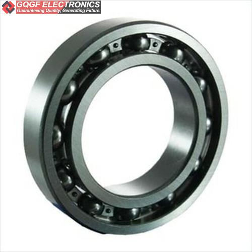
At first glance, a deep groove ball bearing seems an odd centerpiece for an electronics tutorial. But the HJ50-R&M (R&M Imperial, 50x130x31mm) is a precision mechanical component that demands a precision electrical drive. Its 50mm bore, 130mm OD, and 31mm width give it a high radial load capacity (approx. 95 kN static) and moderate speed rating (≈3,000 RPM with grease lubrication). This makes it perfect for a motorized spindle test rig—a practical circuit that drives a brushless DC (BLDC) motor mounted on the bearing, measures vibration via an accelerometer, and logs temperature. The tutorial teaches you how to design a sensor-fused motor controller with proper current sensing, filtering, and protection—all while respecting the bearing’s mechanical limits.
Design Requirements & Specifications
Your circuit must:
- Drive a 24V, 2A max BLDC motor (fits the 50mm bore) using a three-phase inverter.
- Read a MEMS accelerometer (ADXL345) at 1kHz to detect vibration anomalies.
- Monitor bearing temperature with a 10k NTC thermistor (range -40°C to +125°C).
- Operate from a 24V DC supply with 1% ripple, and include overcurrent (2.5A) and over-temperature (85°C) shutdown.
- Provide a UART interface (115200 baud) for data logging to a PC.
Key electrical specs: Motor phase resistance = 0.5Ω, inductance = 100µH, max speed 3,000 RPM → electrical frequency = 150Hz (for a 4-pole motor). PWM frequency set to 20kHz to avoid audible noise and to keep current ripple under 10%.
Step-by-Step Design Process with Calculations
1. Current sensing: Place a 0.05Ω shunt resistor in the low-side of the inverter. At 2A, the sense voltage = 0.05 × 2 = 0.1V. Use an INA240 current sense amplifier (gain 20) → output = 2.0V at full load. A differential filter (R=1kΩ, C=10nF, cutoff ≈ 16kHz) removes PWM spikes.
2. Gate drive: Use IR2104 half-bridge drivers. Bootstrap capacitor: C_boot = 10 × Q_g / ΔV = 10 × 25nC / 12V ≈ 21nF → select 100nF (ceramic, X7R). Add a 1Ω gate resistor to slow switching and reduce EMI.
3. Thermistor interface: Use a voltage divider with 10kΩ pull-up to 3.3V. At 25°C, Vout = 1.65V. For 85°C (NTC resistance ≈ 1.45kΩ), Vout = 3.3 × 1.45 / (10+1.45) = 0.42V. ADC resolution (12-bit) gives 0.8°C per step—adequate.
4. Accelerometer: ADXL345 set to ±16g, output data rate 1.6kHz. Use SPI at 5MHz. Add a 100nF decoupling cap on VDD and a 2.2µF on VDD_IO.
Component Selection Rationale for Complete BOM
- MCU: STM32F103C8 (“Blue Pill”) — cheap, has 3 ADCs, 4 timers for PWM, and SPI. Plenty of GPIO for fault flags.
- MOSFETs: IRFZ44N (55V, 49A) — overkill but low Rds(on)=0.022Ω, so conduction loss at 2A is 0.088W per FET. Use a D2PAK heatsink tab.
- Gate driver: IR2104 — half-bridge, high-side bootstrap, undervoltage lockout. One per phase.
- Shunt resistor: 0.05Ω, 2W, metal film — low inductance (10nH).
- Sense amp: INA240A1 — fixed gain 20, high common-mode rejection, excellent for PWM rejection.
- Accelerometer: ADXL345 breakout (3.3V logic).
- NTC: Vishay NTCLE100E3103JB0 (10k ±5%).
- Supply filtering: 470µF electrolytic + 100nF ceramic at the 24V input; add a 3.3V LDO (AMS1117) for logic.
Simulation Tips & What to Look For
Use LTspice. Simulate the power stage: build a simple BLDC model as three back-EMF sine sources (150Hz) in series with R=0.5Ω, L=100µH. Drive with three PWM sources (20kHz) with 120° commutation. Watch for:
- Current ripple in the shunt: should be < 200mA peak-to-peak. If larger, increase PWM to 30kHz or add a 1µH series inductor.
- Bootstrap voltage: simulate the IR2104’s V_BS and ensure it stays above 8V during high-side on-time.
- Thermal: use a behavioral resistor with temp coefficient to see if the thermistor divider output stays within ADC range.
- Also simulate the INA240 output: ensure it swings 0.1V to 2.0V without clipping (supply is 5V).
Prototype Build & Testing Methodology
1. Breadboard the MCU + sensor first — verify UART prints raw ADC values. Calibrate NTC using two known temps (ice bath 0°C, boiling 100°C). Fit the Steinhart-Hart equation.
2. Build the power stage on a perfboard with thick traces for 24V and motor phases. Keep gate driver traces < 2cm. Add a 0.1µF snubber across each MOSFET drain-source.
3. Open-loop test: Run motor at 10% duty, no load. Measure phase current with a clamp meter. Verify it’s sinusoidal—if not, adjust commutation timing.
4. Closed-loop speed control: Use a Hall sensor (optional) or back-EMF zero-crossing. Start with a PI loop (Kp=0.5, Ki=0.1) and tune by observing step response on an oscilloscope.
5. Vibration test: Mount ADXL345 rigidly near the bearing housing. Spin at 1,000 RPM. Record FFT—look for a peak at 16.7Hz (1,000/60) and harmonics. Any peak above 1g RMS indicates bearing wear or misalignment.
Performance Verification & Optimization
- Thermal: Run at rated 2A for 30 minutes. Bearing temp should stabilize below 60°C (ambient 25°C). If hotter, reduce speed or add forced air.
- Current ripple: Measure across shunt with a differential probe. Ripple should be <10% of 2A (200mA). If higher, increase PWM frequency to 25kHz.
- Efficiency: Measure DC input power (24V × I_in) vs. mechanical output (torque × speed via dynamometer). Expect >80% at full load. Optimize dead-time in gate drivers (start at 500ns, reduce to 200ns if no shoot-through).
- EMI: Add a common-mode choke (e.g., 1mH) on the 24V input. Retest vibration signal—noise floor should drop below 10mg.
- Bearing health algorithm: Store baseline FFT. Compute RMS of vibration in 1-10kHz band. If it increases by 20% over 100 hours, flag a maintenance alert via UART.
Final Notes
This project teaches you to bridge mechanical and electrical design. The HJ50-R&M bearing is robust enough for repeated prototyping, yet its precision forces you to clean up your PWM, grounding, and signal conditioning. With the complete BOM (