MEMS Oscillator App Note: 25MHz LVCMOS Design Guide
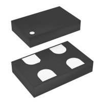
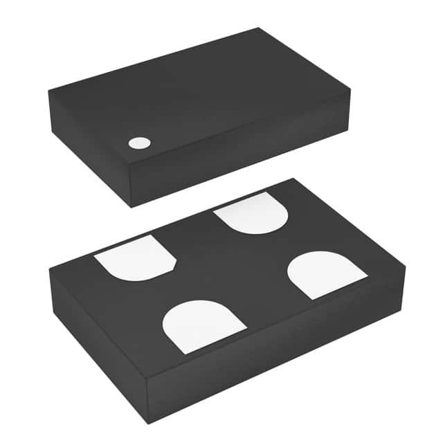
The SIT1618BA-31-33N-25.000000 is a fixed-frequency, 25 MHz MEMS oscillator with an LVCMOS/LVTTL output and a 3.3V supply, ideal for replacing quartz-based XOs in applications where size, shock resistance, and fast startup are priorities. To achieve optimal performance, treat this device as a high-speed digital source, not just a passive crystal. The recommended topology is a straightforward point-to-point connection from the output pin to the clock input of your load, with a series termination resistor placed as close to the oscillator’s output as possible. A 22 Ω to 33 Ω resistor in series is typically sufficient to match the source impedance to the characteristic impedance of the trace (typically 50 Ω) and to reduce ringing on the rising and falling edges. Do not use a parallel termination at the load for a single-ended LVCMOS signal unless your receiver explicitly requires it, as this will unnecessarily load the output and increase power dissipation. The output enable (OE) pin, if available on your specific package variant, should be tied to VDD through a 10 kΩ pull-up resistor if you do not plan to use it, ensuring the oscillator always starts and runs. Bypass the VDD pin with a 100 nF ceramic capacitor placed as close as possible to the VDD and GND pins, and add a 10 µF bulk capacitor at the point where VDD enters the PCB power plane to handle transient current demands.
For supporting passives, choose X7R or C0G dielectric for the 100 nF decoupling capacitor, with a voltage rating of at least 6.3V. The series termination resistor should be a thin-film, 0402 or 0603 size, with a tolerance of 1% to keep impedance matching consistent. Avoid using inductors in the power path; instead, rely on a low-resistance, low-inductance power plane. If you must filter the supply, use a ferrite bead with a DC resistance below 100 mΩ and a rated current above 100 mA, followed by a 100 nF capacitor after the bead. Ensure the load capacitance of the clock receiver is considered—most modern CMOS inputs present a few picofarads, so no external load capacitor is needed. The SIT1618BA is designed to drive up to 15 pF total load without external components. Do not add capacitors to the output trace to ground, as this will slow the edge rates and increase jitter.
PCB layout is critical for signal integrity. Place the oscillator within 5–10 mm of the receiving IC to minimize trace length. Route the output trace as a 50 Ω microstrip over a solid ground reference plane, with no vias in the trace if possible. If a via is unavoidable, use a single via and ensure the return path is continuous by stitching ground vias nearby. Keep the trace width consistent and avoid 90-degree corners; use 45-degree bends or arcs. The ground pin of the oscillator should have a direct, short connection to the ground plane via a thermal-relief pad or a solid via placed immediately adjacent to the pin. Do not route any other high-speed signal parallel to the clock trace for more than 1 cm; maintain a 3x trace-width clearance to other traces. Place the decoupling capacitor on the same layer as the oscillator, with its ground terminal tied directly to the ground plane via a via that is less than 1 mm from the capacitor’s ground pad.
For EMC/EMI, the fast edges (typically 2–3 ns) of the LVCMOS output can generate harmonics well beyond 500 MHz. The series termination resistor is your first line of defense—it reduces overshoot and high-frequency spectral content. Additionally, you may place a small ferrite bead (e.g., 600 Ω at 100 MHz) in series with the output trace, but only after verifying that the added impedance does not violate the receiver’s setup/hold timing. A better approach is to use a “pi” filter on the power supply: a 10 Ω resistor in series with VDD, with 100 nF capacitors on both sides to ground. This isolates the oscillator’s internal switching noise from the rest of the board. Ensure the ground plane under the oscillator is continuous and unbroken—do not split the ground plane underneath the component. If you have a metal chassis, consider adding a shield can over the oscillator and its trace, but ensure the can is grounded at multiple points to avoid acting as an antenna.
Common pitfalls include assuming the MEMS oscillator is “just like a crystal.” Unlike a passive crystal, this is an active device that requires a clean power supply; noise on VDD will directly modulate the output phase. Another frequent mistake is routing the clock trace near a switching regulator or an I/O connector—keep it away from these sources of magnetic and electric field coupling. Also, do not exceed the absolute maximum supply voltage of 3.63V; a 3.6V LDO with a 5% tolerance is too risky. Use a dedicated 3.3V rail with ±5% regulation. Finally, do not leave the OE pin floating—it may pick up noise and cause the output to disable intermittently.
For prototyping, start with a solder-down evaluation board or a breakout board that matches the SIT1618BA’s footprint. Power the oscillator from a clean bench supply set to 3.3V, and use a short, 50 Ω coax cable from the output to a high-impedance oscilloscope probe (10x, 1 MΩ). Measure the output waveform for amplitude (should be rail-to-rail, typically 0V to 3.3V), rise/fall times (should be < 4 ns), and overshoot (should be < 10%). Use a spectrum analyzer with a near-field probe to check for harmonic spurs. For timing validation, use a frequency counter with a gate time of 1 second to verify the 25 MHz frequency is within ±50 ppm (or the specified tolerance) at room temperature. Test the startup time by turning on the supply and measuring the time to first valid clock edge; the SIT1618BA typically starts in under 2 ms. Finally, perform a temperature sweep from -40°C to +85°C in a thermal chamber, checking that the frequency does not deviate beyond the datasheet limit. If you see jitter on the scope, verify that your probe ground lead is as short as possible—a long ground clip will pickup noise and give false readings.