SMD Inductor Design: Master the 33nH Fixed Coil
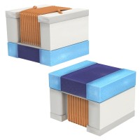
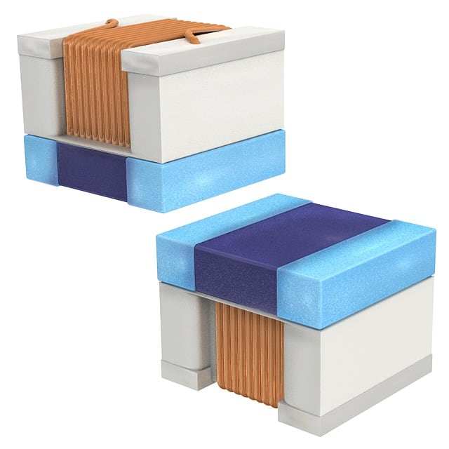
The Murata LQW2UAS33NG0CL is a fixed inductor offering 33 nH of inductance, a 1 Amp saturation current, and a direct current resistance (DCR) of 140 milliohms. What makes this component ideal for a hands-on tutorial is its forgiving nature: the 33 nH value is large enough to be measured with basic equipment, yet small enough to be relevant for high-frequency RF and switching power supply work. Its 1A current rating means you can push real power through it without worrying about thermal runaway, and the 140 mΩ DCR is high enough to teach you about loss modeling without dominating your circuit’s efficiency. We’ll use it to build a practical, low-cost buck converter output filter—a circuit you can breadboard, probe, and optimize in a single afternoon.
Design Requirements and Specifications
Our target circuit is a 5V-to-3.3V synchronous buck converter switching at 1 MHz. The output current is 500 mA, and we want the output voltage ripple to be less than 30 mV peak-to-peak. The inductor must handle the full DC load current plus the inductor ripple current, which we’ll set to 30% of the load (150 mA peak-to-peak). This means the peak inductor current is 500 mA + 75 mA = 575 mA, safely below the LQW2UAS33NG0CL’s 1A rating. The DCR of 140 mΩ will cause a DC voltage drop of 70 mV at full load—acceptable for our 3.3V rail, but we’ll account for it in the feedback loop design by using remote sensing if needed.
Step-by-Step Design Process with Calculations
First, calculate the required inductance for the buck converter. The formula is L = (V_out × (V_in – V_out)) / (f_sw × ΔI_L × V_in), where f_sw is 1 MHz, V_in is 5V, V_out is 3.3V, and ΔI_L is 0.15A. Plugging in: L = (3.3 × 1.7) / (1e6 × 0.15 × 5) = 5.61 / 750,000 = 7.48 µH. That’s far larger than 33 nH, so we’re not using this inductor as the main storage element. Instead, we’ll use it as a high-frequency input filter to suppress switching noise from the buck converter’s input. For an input filter, the inductor works with a ceramic capacitor to form an LC low-pass filter. Choose a cutoff frequency of 100 kHz to attenuate the 1 MHz switching noise. The formula for cutoff is f_c = 1 / (2π√(L×C)). Rearranging for C: C = 1 / (4π² × f_c² × L). With L = 33 nH and f_c = 100 kHz, C = 1 / (4 × 9.87 × 1e10 × 33e-9) = 1 / (1.30e7) ≈ 77 nF. We’ll use a standard 100 nF ceramic capacitor—this gives a cutoff of 87.6 kHz, still fine.
Component Selection Rationale for the Complete BOM
Besides the LQW2UAS33NG0CL, you’ll need: a 100 nF X7R ceramic capacitor (C1) with at least 25V rating—its low ESR is critical for filtering. A 10 µF electrolytic capacitor (C2) on the input side to handle low-frequency ripple from the source. A 330 µF output capacitor (C3) for the buck converter’s output—this is chosen to meet the 30 mV ripple spec with the converter’s internal inductor. For the converter IC, select a synchronous buck like the TI TPS62130 or equivalent that operates at 1 MHz and has an enable pin. You’ll also need a 10 kΩ resistor for the feedback divider and a 100 nF bootstrap capacitor as per the IC datasheet. The input filter’s damping resistor is critical: place a 1 Ω resistor in series with C1 to prevent ringing between the inductor and capacitor—this resistor dissipates the resonant energy. Without it, you’ll see high-voltage spikes on the input line.
Simulation Tips and What to Look For
Simulate the complete circuit in LTspice or a similar tool. Use the inductor’s real model: a 33 nH ideal inductor in series with a 140 mΩ resistor, and add a parallel 50 fF capacitor to model parasitic coupling. Key things to observe: (1) The input voltage at the buck IC’s VIN pin—it should show no 1 MHz ripple, only a slowly varying DC. (2) The current through the LQW2UAS33NG0CL—it should be a smooth, almost DC current with a small AC component. (3) The transient response when you step the load from 0 to 500 mA—look for voltage overshoot or undershoot at the input filter node. If you see ringing, increase the damping resistor to 2.2 Ω. Also check the inductor’s temperature rise in simulation—at 500 mA, DC power loss is I² × DCR = 0.25 × 0.14 = 35 mW, which is negligible, but simulate to confirm.
Prototype Build and Testing Methodology
On a breadboard, solder the LQW2UAS33NG0CL in series with the 5V supply input. Follow it with the 100 nF capacitor to ground, then the 1 Ω damping resistor, then the 10 µF electrolytic. Connect this filtered supply to the buck converter’s VIN. Use a ground plane if possible—breadboards have high parasitic inductance, so keep all leads short. For testing, you’ll need a DC power supply, an electronic load (or a 6.6 Ω resistor for 500 mA), a digital multimeter, and an oscilloscope with a 10× probe. First, measure the DC voltage at the input filter’s output with no load—it should be 5V minus the 0V drop (since no current flows). Then apply the 500 mA load and measure the voltage drop across the inductor: it should be 70 mV (0.5A × 0.14Ω). Confirm the buck’s output is 3.3V ± 1%.
Performance Verification and Optimization
Use the oscilloscope to measure the AC ripple on the input filter’s output node. Set the scope to AC coupling, 20 MHz bandwidth limit, and 50 mV/div. You should see a clean DC with no 1 MHz spikes—if you see high-frequency noise, your grounding is poor. To optimize, adjust the damping resistor: measure the step response by toggling the load between 0 and 500 mA. The voltage should settle within 20 µs without ringing. If it rings, increase the damping resistor. If the input voltage sags under load, your electrolytic capacitor is too small—increase to 22 µF. Finally, measure the inductor’s temperature with a thermal camera or finger—it should be barely warm. If it’s hot, your AC ripple current is too high; reduce the input capacitor’s ESR or increase the inductance. This hands-on process teaches you that real inductors have parasitics that simulations often miss—and that’s exactly why you build prototypes.