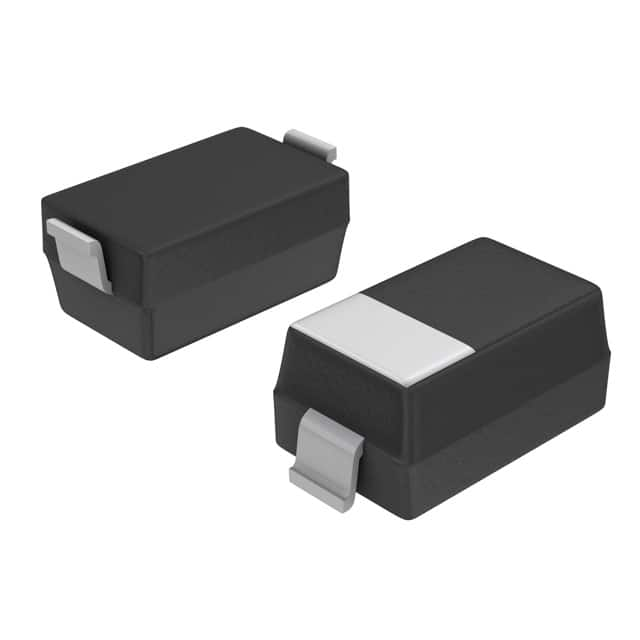
BZT52-C10 SOD-123 Zener: Application Note & Design Guide
The BZT52-C10 from Panjit International Inc. is a 10V, 500mW Zener diode housed in the compact SOD-123 surface-mount package. Its primary role in modern circuits is voltage regulation, reference generation, or as a low-cost protection clamp. The most common and recommended topology is the simple shunt regulator, where the Zener is placed in parallel with the load and a series resistor (R1) connects the unregulated supply to the cathode of the Zener. For this configuration to work correctly, the input voltage (VIN) must be at least 2 to 3 volts above the 10V Zener voltage, and the series resistor must be chosen to satisfy two conflicting constraints: it must allow enough current to keep the Zener in breakdown (typically 5mA to 20mA for stable operation) while also limiting the maximum power dissipation to under 500mW. The formula R1 = (VIN(min) – 10V) / (ILOAD(max) + IZ(min)) provides the upper bound for resistance, while R1 = (VIN(max) – 10V) / (IZ(max)) gives the lower bound to prevent exceeding the power limit. Always bias the device with at least 5mA of Zener current to ensure the dynamic impedance is low and the output voltage remains tight.
When selecting supporting passives, the series resistor is the most critical component. Choose a resistor with a suitable power rating—calculate the worst-case power as (VIN(max) – 10V)² / R1 and derate by at least 50%. A standard 0805 or 1206 thick-film resistor is usually adequate for currents up to 20mA. For the input capacitor, place a 100nF ceramic (X7R or C0G) directly at the cathode to improve transient response and reduce high-frequency noise from the supply. If the circuit is battery-powered or prone to fast load steps, add a 10µF electrolytic or tantalum in parallel with the 100nF. For the output side, a 1µF ceramic capacitor across the Zener is beneficial; however, be cautious—too large a capacitance (above 10µF) can cause the Zener to oscillate or fail to clamp fast transients because the capacitor delays the voltage rise at the cathode, allowing the Zener to conduct excessively during power-up. Always place these capacitors as close to the Zener’s pins as physically possible, using short, wide traces to minimize parasitic inductance.
PCB layout for the SOD-123 package is straightforward but requires attention to thermal and parasitic paths. The SOD-123 has a small thermal pad on the cathode side; ensure that the copper pour connected to the cathode is as large as practical to act as a heat sink. For a 500mW device operating at 200mW continuous, a minimum of 10mm² of copper on the top layer, with a few thermal vias to an inner ground plane, will keep the junction temperature well below the 150°C absolute maximum. Route the series resistor and the Zener in a straight line from the input source to the load, avoiding sharp 90-degree bends that create inductance. Keep the loop area between the Zener, the series resistor, and the input capacitor as small as possible; this reduces radiated emissions and improves clamping speed. If the Zener is used as an ESD clamp on a signal line, place it directly at the connector, with the cathode to the signal and the anode to ground, and ensure the ground connection is a low-impedance via to the ground plane—do not share this via with other noisy return currents.
For EMC/EMI, the BZT52-C10 is inherently a low-noise component, but its effectiveness as a transient suppressor depends on layout and circuit parasitics. The Zener’s breakdown voltage has a positive temperature coefficient (approximately +1mV/°C for a 10V device), which means it becomes less effective at clamping high-energy surges at elevated temperatures. To mitigate this, never rely solely on the Zener for high-energy ESD or surge events (e.g., IEC 61000-4-2 level 4). Instead, place a series resistor (e.g., 10Ω to 100Ω) before the Zener to limit peak current, and consider adding a small ferrite bead in series with the input line to damp high-frequency ringing. For conducted emissions, the 100nF input capacitor should be a low-ESL type, and a common-mode choke can be added if the supply leads are long. When the Zener is used as a voltage reference, bypass the cathode with a 10nF film capacitor to filter white noise; do not use a ceramic X7R here because its voltage coefficient can cause microphonic or voltage-dependent capacitance artifacts. Avoid creating a ground loop by ensuring the Zener’s anode connects to the same ground point as the load’s return, preferably via a star-point connection.
One of the most frequent design pitfalls is confusing the Zener’s power rating with its surge capability. The 500mW rating applies to DC or continuous operation; a single 10µs, 1A pulse can cause instantaneous heating and device failure if the energy exceeds the pulse power curve. Always verify the surge capability in the datasheet—for the BZT52 series, typical peak pulse power is around 200W for a 10/1000µs waveform, but this drops off rapidly for longer durations. Another common error is using a Zener as a series regulator, which it is not; it must always be used in shunt. Also, beware of reverse insertion: the SOD-123 package has a cathode band, and if placed backwards, the device will behave like a forward-biased diode, clamping at ~0.7V and potentially shorting the supply. Always double-check the orientation during assembly and prototyping.
For prototyping and bench testing, begin by assembling the shunt regulator on a minimal breadboard or, preferably, a soldered prototype PCB to avoid parasitic inductance. Use a variable DC power supply set to 12V, and measure the Zener voltage with a multimeter—it should read 10V ± 5% (i.e., 9.5V to 10.5V) when biased with 10mA. Use a current probe or measure the voltage across the series resistor to confirm the current is within the safe range. To test transient response, apply a square wave load from 0 to 20mA using a fast MOSFET switch and observe the output on an oscilloscope with a 10x probe (set to 1MΩ input impedance); you should see less than 100mV of droop. For ESD testing, use a simple contact discharge gun at 2kV and verify the Zener clamps the voltage to under 15V without latching or destruction. Finally, perform a thermal test: run the circuit at maximum continuous load for 30 minutes and measure the case temperature with a thermocouple; it should stay below 100°C. If it exceeds this, increase the copper area or reduce the Zener current. These steps will ensure the BZT52-C10 operates reliably in your final product.