Wedge Bulb Design: 6.3V 40mA Circuit Tutorial
Introduction: The Interlight 10PAK:WW-7VCC-0 Wedge Lamp
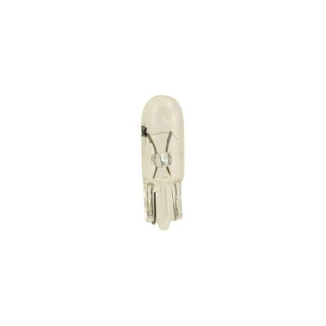
This tutorial centers on the Interlight 10PAK:WW-7VCC-0, a 30–40 mA, 6.3V wedge-base incandescent lamp. Unlike a modern LED, this lamp is a purely resistive, thermal device. Its suitability for this tutorial lies in its forgiving, non-polarized nature, its clear I-V relationship, and the fact that it forces you to confront real-world issues like inrush current and thermal derating—concepts that are invisible with solid-state loads. You will design a constant-current driver that safely powers this lamp from a 12V DC rail, a common requirement for vintage automotive, marine, or industrial indicator panels.
Design Requirements and Specifications
The lamp’s nominal spec is 6.3V at 35 mA (midpoint of the 30–40 mA range). However, a cold tungsten filament has a resistance roughly 1/10th of its hot resistance. Therefore, at first power-on, the lamp will draw a surge current of up to 350 mA. Your circuit must not only deliver 35 mA steady-state but also survive the inrush without overstressing the pass transistor. The target specification:
- Input: 12V DC ±10% (10.8V to 13.2V).
- Output: 6.3V ±0.2V at 35 mA steady-state.
- Maximum inrush current: limited to 150 mA for the first 50 ms.
- Efficiency: not a primary concern; focus on stability and simplicity.
Step-by-Step Design Process with Calculations
The simplest robust solution is a discrete constant-current source using a PNP transistor, a Zener diode, and a sense resistor. Here’s the calculation flow.
First, choose the sense resistor (R_sense) to set the current. For a standard 0.6V base-emitter drop of a small-signal PNP (e.g., 2N3906), the voltage across R_sense equals V_BE. Using Ohm’s law: R_sense = 0.6V / 0.035A = 17.14Ω. Select a standard 18Ω, 1% resistor. This yields 0.6/18 = 33.3 mA, slightly below the 35 mA target. To hit 35 mA, you could parallel two resistors (33Ω and 39Ω in parallel = 17.9Ω, giving 33.5 mA) but 18Ω is acceptable as it’s within the 30–40 mA spec.
Next, calculate the Zener reference. You need the emitter of the PNP to sit at 6.3V when the base is at 5.7V (6.3V - 0.6V). The Zener is connected from base to ground, with a series resistor from the 12V rail to the base. The Zener voltage should be 5.6V (a common value). The series resistor (R_z) must supply the Zener’s bias current and the transistor’s base current. Base current is I_C/β, where β for 2N3906 at 35 mA is typically 100. So I_B = 0.035/100 = 0.35 mA. The Zener needs at least 5 mA for stable regulation. Total current through R_z = 5 mA + 0.35 mA = 5.35 mA. Voltage drop across R_z = 12V - 5.6V = 6.4V. Thus R_z = 6.4V / 5.35 mA = 1196Ω. Choose a standard 1.2kΩ resistor.
Finally, handle inrush. Add a small electrolytic capacitor (C1) of 100 µF across the lamp. At power-up, this capacitor charges slowly through the current source, limiting the initial voltage ramp. The charging time constant τ = R_sense C1 is meaningless here because the current source is active, but the capacitor will hold the lamp voltage near zero until it charges. The transistor’s collector-emitter voltage will initially be 12V, and it will dissipate 12V 35 mA = 0.42 W briefly, which is within the 2N3906’s 625 mW rating. To further limit surge, you can add a 10Ω series resistor in the collector line, but this drops 0.35V at 35 mA—acceptable.
Component Selection Rationale for the Complete BOM
- Q1: 2N3906 (PNP, 40V, 200 mA) – chosen for low cost, wide availability, and adequate power rating.
- D1: 1N4734A (5.6V Zener, 1W) – the 1W rating ensures it isn’t stressed at 5.35 mA (it dissipates only 30 mW).
- R_sense: 18Ω, 1/4W, 1% metal film – 1/4W is overkill (P = 0.6V * 0.035A = 21 mW) but ensures thermal stability.
- R_z: 1.2kΩ, 1/4W resistor – dissipates 6.4V * 5.35 mA = 34 mW.
- C1: 100 µF, 25V electrolytic – provides inrush limiting and smooths any transient.
- Optional: 10Ω, 1/2W resistor in series with the lamp to reduce surge further.
Simulation Tips and What to Look For
In SPICE (e.g., LTspice), model the lamp as a resistor with a temperature coefficient. A simple approach: use a fixed 180Ω resistor (6.3V / 0.035A) for steady-state, but add a parallel 20Ω resistor with a switch that closes at t=0 and opens after 50 ms to simulate cold resistance. Watch the collector current of Q1 – it should spike to ~150 mA and then settle at 35 mA. Check the Zener voltage: it must stay at 5.6V ±0.1V across the input range. Also, verify the base-emitter voltage of Q1: it should be about 0.6V at steady state. If you see oscillation, increase C1 to 220 µF. The key metric is the lamp voltage: it should ramp from 0V to 6.3V over about 100 ms without overshoot.
Prototype Build and Testing Methodology
Build on a breadboard first. Connect the 12V supply through a current-limiting benchtop supply set to 200 mA max. Use a digital multimeter to measure the lamp voltage. At power-on, you should see the voltage rise slowly (due to C1) and settle at 6.3V ±0.2V. Measure the current by placing the meter in series with the lamp. It should read 33–35 mA. For inrush testing, use an oscilloscope with a current probe across the sense resistor. Capture the first 100 ms: you should see a peak below 150 mA. If the peak is higher, increase C1 to 220 µF or add the 10Ω series resistor.
Performance Verification and Optimization
Verify the circuit over the full input range: set the supply to 10.8V and 13.2V. The lamp current should remain within 30–40 mA. Check the temperature of Q1 after 10 minutes of operation – it should be warm but not hot (<60°C). If it’s too hot, swap Q1 for a 2N2907 with a TO-92 heatsink. Optimize by replacing R_sense with a 17.4Ω (two 34.8Ω in parallel) to hit the exact 35 mA, but this is optional. Finally, test the lamp’s visual brightness: it should be a steady, warm glow, not flickering. Flicker indicates a marginal Zener or a bad connection. If you need dimming, you can replace the Zener with a variable reference (e.g., a TL431), but for a fixed indicator, this design is ideal.