Mastering the CGA4J3X7R1H474M125AB: A 0805 Capacitor Datasheet Guide
The CGA4J3X7R1H474M125AB from TDK is a surface-mount multilayer ceramic capacitor (MLCC) that exemplifies the balance between volumetric efficiency and electrical robustness required in modern electronic designs. At its core, this component offers a capacitance of 0.47 microfarads (µF) with a ±20% tolerance, designated by the 'M' code. This tolerance is standard for X7R dielectric Class II capacitors and is perfectly acceptable for power supply decoupling, filtering, and signal coupling where absolute precision is not critical. The rated DC voltage of 50V is a key differentiator; it means the component can continuously withstand 50 volts DC across its terminals under normal operating conditions. In practice, this provides a substantial safety margin for 12V, 24V, or even 48V power rails, but it is crucial to remember that this rating assumes an ambient temperature within the specified range—typically up to 125°C for X7R. The X7R temperature characteristic, defined by EIA standards, guarantees that capacitance will not deviate by more than ±15% from its nominal value over a temperature range of -55°C to +125°C. This is critical for engineers who need predictable behavior across harsh environmental extremes, though it is less stable than C0G (NP0) dielectrics.
When interpreting absolute maximum ratings, the 50V rating is the maximum continuous working voltage, not a surge rating. Applying a voltage exceeding this, even momentarily, can lead to dielectric breakdown and catastrophic short-circuit failure. However, the more insidious concern for X7R capacitors is DC bias derating. Unlike film or electrolytic capacitors, Class II ceramic capacitors exhibit a significant reduction in effective capacitance as a DC voltage is applied. At 50V DC bias, the actual capacitance of this 0.47µF part can drop by as much as 60-70%, potentially leaving you with an effective capacitance of only 0.15-0.19µF. This is a fundamental property of the ferroelectric ceramic material. Therefore, in a design, you must always select the capacitor based on its capacitance at the operating DC voltage, not its nominal value. For a 50V-rated part operating at 24V, the derating is less severe—perhaps a 20-30% drop—but it is still non-negligible. Additionally, do not apply reverse polarity voltage, as this will permanently damage the dielectric. There is also a ripple current rating, though it is not explicitly stated in the datasheet as a single number; instead, it is derived from the capacitor's equivalent series resistance (ESR) and its ability to dissipate heat. Excessive ripple current can cause self-heating, which accelerates aging and reduces reliability.
In a typical application circuit, this capacitor is most commonly used for power supply decoupling on a 12V or 24V bus. For example, placed directly across the VCC and GND pins of an operational amplifier, a microcontroller, or a DC-DC converter's input, its low ESR and low ESL at high frequencies will shunt high-frequency noise to ground, preventing it from corrupting sensitive analog or digital signals. The X7R dielectric's stable temperature coefficient ensures that its filtering performance remains consistent even as the board heats up. In a series coupling application, the 0.47µF value will pass AC signals while blocking DC bias, but you must verify that the high-pass filter cutoff frequency (f = 1/(2πRC)) aligns with your signal bandwidth. The 50V rating makes it an excellent choice for automotive applications (e.g., 12V battery lines with load-dump transients) or industrial sensors operating on 24V rails, where voltage spikes are common. Always place the capacitor as close as possible to the power pin, with a low-inductance ground via, to maximize its effectiveness.
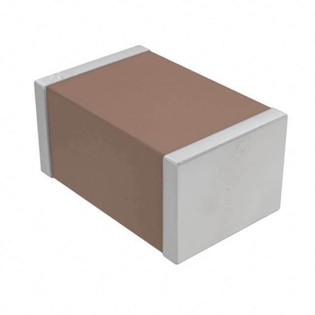
The package is an 0805 (2012 metric) footprint, which is a robust, industry-standard size that is easy to assemble and inspect. The pin configuration is inherently simple—it is a two-terminal device with no polarity. However, for mechanical reliability, pay attention to the termination style. The 'A' suffix in the part number indicates a soft termination or flexible termination, which is designed to absorb board flexure stress. This is critical in automotive or high-vibration environments where PCB bending can crack the ceramic body. The soft termination uses a conductive resin layer between the ceramic and the metal termination, preventing crack propagation. For soldering, the component is rated for lead-free reflow soldering with a peak temperature of 260°C. During reflow, ensure the temperature ramp rate does not exceed 3°C/second to avoid thermal shock. After soldering, avoid mechanical stress on the solder joints; the component should not be used as a strain gauge to test board flexibility.
Thermal management is often overlooked for small capacitors, but it is vital. The X7R dielectric has a maximum operating temperature of 125°C, and this is the limiting factor for power dissipation. The capacitor itself generates heat due to I²R losses from ESR when carrying ripple current. If the ambient temperature is already 85°C, the allowable temperature rise is only 40°C. For a given ripple current, the power dissipated is P = I_rms² × ESR. The ESR of this part is typically in the range of 10-30 milliohms at 1 MHz, which is low, but at high switching frequencies in a buck converter, the RMS current can be substantial. Use the thermal impedance of the 0805 package—typically around 50-70°C/W—to estimate the temperature rise. If the capacitor gets too hot, capacitance will drift, and the likelihood of dielectric aging increases. Always provide good copper pouring around the pads to act as a heat sink.
Finally, the datasheet's characteristic curves are your primary tool for accurate design. The most important graph is Capacitance vs. DC Bias Voltage. This curve shows the effective capacitance drop as a function of applied DC voltage; you must read the capacitance value at your specific operating voltage. Next is the Capacitance vs. Temperature curve, which shows the ±15% variation across -55°C to +125°C. This is not a linear relationship; it typically peaks near room temperature and dips at the extremes. The Impedance and ESR vs. Frequency curves are crucial for decoupling design. You will see a self-resonant frequency (SRF) typically around 5-10 MHz for this value; above SRF, the capacitor becomes inductive, and its filtering ability degrades. The ESR curve shows a minimum near SRF, which is where the capacitor is most effective at damping high-frequency noise. By cross-referencing these curves, you can predict the capacitor's real-world behavior with high fidelity, ensuring your circuit operates reliably over its entire life and temperature range.