AC/DC Converter Design: 1200W Multi-Voltage Tutorial
Introduction to the Component
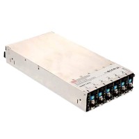
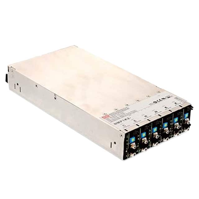
The MEAN WELL NMP1K2-EHECCK-00 is not a simple DC-DC converter; it is a modular, configurable AC/DC power supply platform capable of delivering up to 1200W across four independent outputs. The part number tells you everything: the “EHECCK” suffix defines the output configuration—specifically, two 12V outputs (E and H), one 24V output (E), and one 5V output (C), with the final “K” indicating a specific current limit set. What makes this ideal for a hands-on tutorial is its built-in flexibility: you can mix and match output voltages and currents without redesigning the power stage. For a practical engineer, this is a masterclass in system-level power budgeting, thermal management, and load regulation—because you are not designing the magnetics or the control loop, but you must design the surrounding circuitry, protection, and load distribution correctly to exploit its full capability.
Design Requirements and Specifications
Let’s design a laboratory bench power distribution unit for an automated test rig. The system requires: +12V at 10A for motors, +12V at 3A for logic (isolated from motor supply to prevent noise), +24V at 5A for pneumatic solenoids, and +5V at 15A for digital circuitry. Total continuous power: (12×10) + (12×3) + (24×5) + (5×15) = 120 + 36 + 120 + 75 = 351W, well under the 1200W rating—but you must check the module’s per-output current limits. From the datasheet, the NMP1K2’s “E” slots (12V) are rated 20A each, the “H” slot (24V) is rated 10A, and the “C” slot (5V) is rated 40A. Our loads are within limits, but we need to design for peak inrush (motor stall, solenoid surge) and ripple rejection (especially for the 5V logic rail). Also, the AC input is universal (90-264VAC), so we will design for 230VAC operation to maximize efficiency.
Step-by-Step Design Process with Calculations
1. Output wiring and sense lines: Each output has remote sense terminals (S+ and S-). For the 12V motor rail, use remote sensing to compensate for voltage drop in the power cables. Calculate cable resistance: if you use 2m of 2.5mm² copper (0.007Ω/m round trip), drop at 10A is 0.14V. That is 1.2%—acceptable without sense, but using sense lines reduces it to near zero. Connect S+ and S- directly to the load’s power terminals, not to the PCB.
2. Output filtering: The NMP1K2 has a switching ripple of ~100mVpp. For the 5V logic rail, add a LC low-pass filter: L=10µH (saturation current >20A), C=470µF electrolytic + 100nF ceramic. Cutoff frequency: f_c = 1/(2π√(LC)) = 1/(2π√(10µH×470µF)) ≈ 2.3kHz—this attenuates the 100kHz switching noise by 40dB. For the motor rail, add a 1000µF electrolytic capacitor to handle transient back-EMF.
3. Protection circuitry: Each output needs an external fuse or circuit breaker. Calculate fuse rating at 125% of continuous load: 12V/10A → 12.5A fuse (use 15A fast-blow), 12V/3A → 4A, 24V/5A → 6.3A, 5V/15A → 20A. Add a TVS diode across each output: for 12V use SMBJ13A (clamps at 21.5V), for 24V use SMBJ26A, for 5V use SMBJ6.0A.
4. Thermal design: Even at 351W, at 90% efficiency the module dissipates 39W. The NMP1K2 has a built-in fan, but you must ensure 20mm clearance around the unit. Calculate airflow: 39W × 0.05 m³/min/W ≈ 2 m³/min—the internal fan provides this, but do not obstruct the vents. Mount the unit on a metal plate to increase heat sink capacity.
5. AC input wiring: Use a 5A input fuse (1200W/230V = 5.2A, derate to 80% → 6.5A, so use 8A). Add a 275VAC varistor (MOV) across the input for surge protection.
Component Selection Rationale
For the LC filter inductors, choose a Würth Elektronik 7443641000 (10µH, 20A saturation, 2.5mΩ DCR)—this keeps DC loss below 50mV at full load. Capacitors: use Nichicon UHE series electrolytics (low ESR, 105°C rated) for long life. The TVS diodes from Littelfuse (SMBJ series) are selected for their fast response (<1ns). For fuses, use Littelfuse 3AB fast-acting with holder, not PCB-mount, for easy replacement. The AC input connector is a IEC C14 inlet with integrated fuse holder. For the DC output connectors, use Anderson Powerpole connectors (45A rating) for the motor and 24V rails, and a screw terminal block for the 5V rail. All wiring uses silicone-insulated, high-flex wire rated for 105°C.
Simulation Tips and What to Look For
Since the NMP1K2 is a closed module, you cannot simulate its internal control loop. Instead, simulate your external circuitry:
- In LTspice, model the module as an ideal DC source with a series output impedance (e.g., 10mΩ) and a 100mVpp, 100kHz ripple source.
- Simulate the LC filter and check the output voltage ripple at the logic rail. Look for ringing—if the filter’s Q factor is too high (damping too low), you will see overshoot on load steps. Add a 0.1Ω series resistor (or use a ferrite bead) to damp it.
- Simulate the inrush current when a motor starts (model as a step load from 1A to 10A with 10ms rise time). Verify that the output voltage dip stays within ±5% (for 12V, that’s 0.6V). If not, increase the bulk capacitance.
- Check the TVS diode’s clamping voltage under a simulated 24V solenoid kickback (model as a 60V spike). Ensure the TVS conducts and clamps below the module’s absolute maximum rating (which is 125% of nominal, so 30V for 24V rail).
Prototype Build and Testing Methodology
Build the circuit on a perfboard or custom PCB with the NMP1K2 mounted on a standoff. First, test with no load: connect AC power via a variac (start at 50VAC, ramp to 230V) while monitoring all output voltages with a multimeter. Check that the module’s green “Power OK” LED is lit. Then, apply each load incrementally using electronic loads: start at 10% of rated current, then 50%, then 100%. Use a four-wire Kelvin connection to measure each output voltage at the load point, not at the module terminals. Record the voltage at each step. Also, use a current probe on a scope to check for oscillation—if you see high-frequency ringing on the output, your filter may be unstable. Finally, test the protection: short each output through a wire, and verify the fuse blows (or the module’s internal OCP kicks in—check the datasheet for whether it latches or auto-recovers).
Performance Verification and Optimization
Measure load regulation: at 100% load, the 5V rail should be 5.00V ±0.25V (per datasheet). If it’s high, adjust the trim resistor (the NMP1K2 has a Vout trim pin). For the 12V motor rail, measure the transient response with a 10% to 90% load step: use a 100MHz scope and a