Troubleshooting 8-Circuit Cable Assembly 20″ Z: Key Fixes
Typical Failure Modes and Root Causes
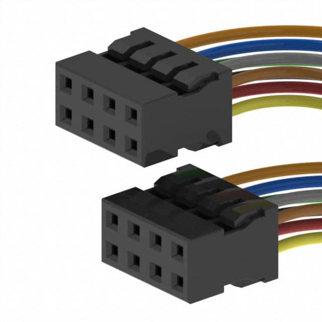
The Molex 0511100850-20-A-6-Z is a 20-inch, 8-circuit cable assembly with pre-crimped leads and a locking connector. In my experience, the most common failure is intermittent open circuits at the crimp barrel-to-wire interface. This happens when the cable is flexed repeatedly near the connector strain relief, causing the wire strands to break inside the insulation while the outer jacket remains intact. Another frequent issue is corrosion on the pin contacts, especially in humid or dusty environments, leading to high resistance and voltage drops. A third failure mode is misalignment of the connector housing – the locking ramp can break if the user forces the connector in at an angle, resulting in poor contact pressure and arcing.
Step-by-Step Debugging Methodology
Start with a visual inspection under a magnifier: check for bent pins, cracked housings, or pulled-back wires. Next, perform a continuity test on each of the 8 conductors with a multimeter, but do this while flexing the cable along its entire length – this catches intermittent breaks. Then, measure insulation resistance between adjacent conductors (should be >100 MΩ) to detect short circuits caused by nicked insulation. If the cable passes static tests, move to a dynamic test: apply a controlled current (e.g., 100 mA) and monitor voltage drop across each line while vibrating the cable harness. Use a digital oscilloscope to catch glitches that a multimeter misses. Finally, if all tests pass, suspect the mating connector on the PCB – use a micro-ohm meter to measure contact resistance at the interface.
Common Mistakes in Schematic Design and PCB Layout
One classic error is sizing the PCB footprint for a different Molex series – the 0511100850 uses a 2.54mm pitch, but some designers mistakenly use 2.0mm holes for a similar-looking part, causing poor seating. Another mistake is placing decoupling capacitors too far from the cable entry point, which creates a long return path for high-frequency noise. On the schematic, designers often forget to include a series resistor or ferrite bead on each line when driving long cables, leading to ringing and false triggering. Also, avoid routing high-speed signals adjacent to power lines on the PCB – this induces crosstalk that mimics a cable fault. Finally, always add a test point or header in series with the cable so you can isolate the harness from the rest of the circuit without desoldering.
Verifying Component Authenticity and Quality
Counterfeit Molex cables are common in the aftermarket. First, check the part number laser marking – genuine parts have a clean, dot-matrix style print that doesn’t rub off. Inspect the connector housing’s mold parting line – fakes often have rough edges. Measure the wire gauge: genuine 0511100850 uses 28 AWG stranded wire, and a micrometer should read ~0.32mm diameter. Test the crimp pull-out force: a genuine terminal should withstand 2 kg pull for 10 seconds. Also, weigh the assembly – authentic cables have a consistent weight (approx. 12 grams); fakes are often lighter due to thinner copper. If you have access to an X-ray fluorescence (XRF) analyzer, check that the gold plating on the contacts is >0.1 micron – counterfeit parts often use nickel only.
Measurement Techniques and Test Equipment
For basic checks, a digital multimeter with 0.1Ω resolution is mandatory. For intermittent faults, use a time-domain reflectometer (TDR) – it can locate a break within 1 inch along a 20-inch cable. A 4-wire Kelvin probe is essential for measuring low resistance (below 100 mΩ) without lead resistance errors. When testing under load, use an electronic load set to 500 mA per line and monitor the voltage with a data logger. For EMI issues, a near-field probe and spectrum analyzer help identify radiation from the cable. Always use a grounded oscilloscope probe with a short ground spring when measuring signals on the cable – long ground leads pick up noise that masks real signal integrity problems.
When to Suspect the Component vs. the Surrounding Circuit
If a single line fails but the other seven are fine, suspect the cable itself – a broken wire or bad crimp. If all lines fail simultaneously, check the mating connector on the PCB or the power supply common return. If the failure only occurs when the system is powered but disappears when unpowered, suspect overcurrent damage – the cable’s insulation may be melted internally. If the fault is intermittent and temperature-dependent (works when cold, fails when hot), it’s likely a crimp that expands with heat. Conversely, if the fault appears after a mechanical shock, it’s a solder joint on the PCB near the connector that cracked, not the cable. A good rule: always test the cable standalone first – disconnect it and jumper a known-good cable. If the system works, the original cable is the culprit. If not, look at the load side.
Real-World Case Studies
Case 1: Intermittent reset in industrial controller. Customer reported random resets. All static tests passed. Using a TDR, I found a break 15 inches from the connector. The wire had fractured due to a zip tie being over-tightened, crushing the insulation. Solution: replace cable and use a spiral wrap instead of tie. Case 2: Corrosion in a greenhouse sensor network. The cable’s contacts showed black tarnish. The root cause was the cable being routed through a condensation-prone area. The housings lacked a seal. We added a conformal coating on the PCB connector and used a dielectric grease on the contacts – problem solved. Case 3: False triggers on a motor encoder. The customer blamed the cable, but an oscilloscope showed 5V spikes on the signal lines caused by the motor’s PWM switching. The cable was fine – we added a 100Ω series resistor and a 1nF cap to ground at the receiver end. Case 4: Counterfeit cable with only 5 conductors actually connected. The cable looked perfect, but three pins had no wire attached – the factory used a dummy terminal. This is why you must always do a full 8-way continuity test before installation, not just a spot check.
In summary, always isolate the cable from the system first, use the right test equipment for the failure mode, and never assume a newly purchased cable is genuine. Document your tests – a simple log of resistance values over time often reveals the root cause faster than any fancy tool.