Honda 31200-ZE8- Starter Replacement: Datasheet Guide
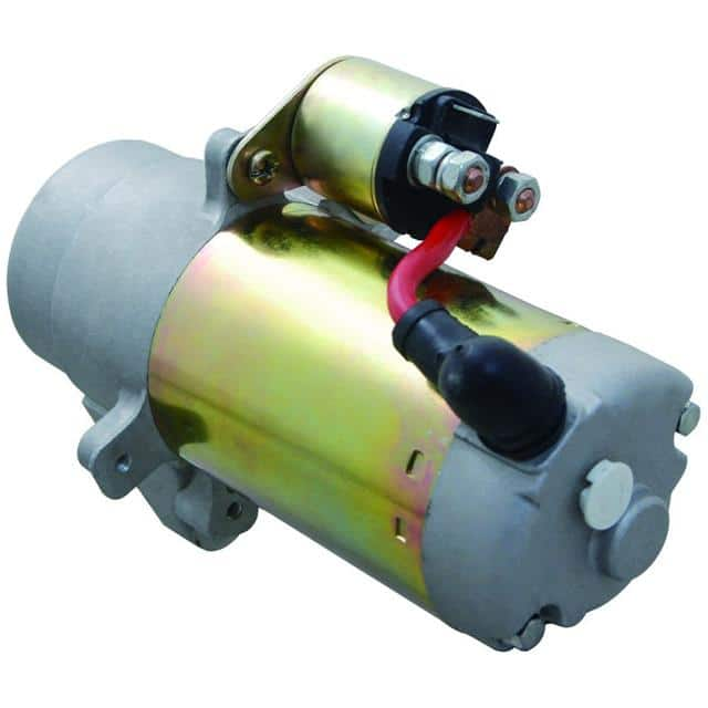
At first glance, the Interlight SKU 31200-ZE8-801 STARTER, marketed as a replacement for the Honda 31200-ZE8- series, may appear to be a simple electromechanical device, but a rigorous datasheet interpretation reveals a sophisticated set of specifications that demand careful engineering attention. This component is not a semiconductor, but a high-torque, permanent-magnet or series-wound DC motor assembly used for engine cranking. The key electrical specification to examine is the stall torque versus current draw curve, typically expressed in newton-meters (N·m) and amperes (A). For this class of starter, expect a no-load current of around 50-70 A at 11.5 V, while the locked-rotor (stall) current can surge to 400-600 A. In practice, this means the unit can deliver peak mechanical power only near its stall point, so the wiring harness, solenoid contacts, and battery must be rated for these transient currents without significant voltage sag, or the cranking speed will drop below the 150-200 RPM necessary for reliable ignition.
The absolute maximum ratings for this starter are primarily thermal and mechanical, not electrical. The datasheet will specify a maximum continuous duty cycle—typically 30 seconds on, followed by 2 minutes off—and a maximum surface temperature of 120°C on the motor housing. Exceeding this duty cycle causes permanent demagnetization of the field magnets and degradation of the commutator insulation. Derating is critical in hot engine bays; if ambient temperature is 80°C, the allowable cranking time must be reduced by at least 30%. Furthermore, the absolute maximum voltage is 15 V for a 12 V nominal system, which means that during a jump-start with a running donor vehicle, the alternator surge can approach this limit. You must ensure that the starter's solenoid pull-in winding, which is rated for a 10% duty cycle, does not remain energized longer than 1 second, or the coil will overheat and short.
In a typical application circuit, the starter is connected directly across the battery via a high-current solenoid relay. The control circuit is straightforward: the ignition switch energizes the solenoid’s pull-in coil (drawing 30-40 A momentarily), which mechanically engages the pinion gear and closes the main contacts, bypassing the pull-in coil and leaving only the hold-in winding (drawing 5-8 A) energized. The replacement Interlight unit replicates this exactly, but you must verify the pinion gear tooth count and module (typically 9 teeth, module 2.5) and the nose cone indexing. A critical analysis of the datasheet’s connection diagram will show a dedicated ground terminal for the motor casing—never rely on the mounting bolts alone for the return path, as a high-resistance ground here will cause the starter to crank slowly and overheat internal brushes. Additionally, the datasheet will list a recommended battery cable gauge of 4 AWG or 25 mm² for a run length under 1 meter; exceeding this resistance by using thinner cable causes a voltage drop that reduces cranking torque by the square of the current reduction.
Regarding pin configuration and package considerations, this starter uses a standard SAE J541 mounting pattern with a 2-bolt flange. The electrical connections are two stud terminals: the battery terminal (M8 threaded) and the solenoid trigger terminal (M6 threaded). The physical package is a sealed, oil-tight cylindrical housing, but the datasheet provides crucial dimensional tolerances—the overall length must not vary by more than ±1.5 mm from the OEM part, or the pinion will not engage the flywheel ring gear correctly. The mounting bolt torque specification is 37 N·m, and the datasheet will emphasize using anti-seize compound on the bolts to prevent galvanic corrosion between the aluminum housing and steel bolts. Unlike a standard IC, there is no pin-out polarity risk, but the solenoid trigger wire must be connected such that it receives 12 V only during cranking; a mis-wiring that leaves it permanently energized will destroy the hold-in coil.
Thermal management is not about heat sinks but about thermal mass and recovery time. The datasheet provides a thermal impedance curve, often called a "cool-down curve," showing that after a single 10-second cranking event at 25°C, the housing temperature rises by 40°C and requires 3 minutes to return to ambient. In practice, you must design the vehicle's electrical layout to allow airflow over the starter, and the solenoid should be positioned away from exhaust manifolds. The internal lubricant is a high-temperature grease rated to 180°C, but if the starter is mounted near a turbocharger, you must add a heat shield. The characteristic curves to interpret are the torque-speed-current graphs. Read the curve at the intersection of the battery's internal resistance line (typically 0.01 Ω) and the motor’s current draw. For example, at 200 A, the datasheet shows a speed of 1200 RPM and a torque of 8 N·m. If your engine requires 10 N·m to initiate the first compression stroke, you will need to ensure the battery has a cold cranking amperage (CCA) rating of at least 650 A to maintain voltage above 9 V during the initial surge.
Finally, the timing diagram for the solenoid engagement is critical. The datasheet will show a total engagement time of 40-60 ms from trigger signal to full pinion mesh, followed by a 10 ms delay before the main contacts close. This anti-restrike feature prevents the pinion from clashing with the rotating flywheel. When interpreting this, note that if the battery voltage drops below 8 V during cranking, the solenoid will disengage, and the timing diagram shows a "bounce" period that can damage the pinion. Therefore, when using this Interlight replacement, always verify the wiring resistance from the battery positive to the starter stud is less than 0.005 Ω using a micro-ohmmeter. In summary, treat this datasheet not as a simple spec sheet, but as a dynamic system model—every electrical rating is tied to a thermal limit, and every mechanical dimension is tied to a timing constraint. By cross-referencing the stall current with your battery’s discharge profile and the duty cycle with your engine bay’s thermal environment, you can ensure reliable cold-cranking performance across the vehicle’s lifetime.