CTSCH875DF-102K Inductor Datasheet: Key Specs & Uses
The CTSCH875DF-102K from Central Technologies is a fixed radial inductor with a nominal inductance of 1000 microhenries (1 mH), a value that places it firmly in the realm of power supply filtering, EMI suppression, and low-frequency signal conditioning. Understanding this component begins with its inductance tolerance, specified as the K suffix, which denotes ±10%. In practice, this means a production batch will yield inductances between 900 µH and 1100 µH at the test frequency, typically 1 kHz or 100 kHz depending on the datasheet’s reference condition. This tolerance is critical when designing resonant circuits or timing networks where precise reactance is non-negotiable; however, for bulk decoupling or DC-DC converter output filtering, the ±10% variation is usually acceptable given adequate loop compensation.
The most consequential specification for any inductor is its saturation current (Isat) and rated DC current (Idc). For the CTSCH875DF-102K, the datasheet will list a maximum DC current, often in the range of 0.1 to 0.3 amperes, at which the inductance drops by a defined percentage, commonly 10% or 30%. You must interpret this carefully: the rated current is not a thermal limit but a magnetic limit. Beyond this point, the ferrite core begins to saturate, causing the inductance to collapse and current to spike, which can lead to overheating or failure in downstream semiconductors. Always derate the operating current to at least 70% of the rated Idc for continuous operation, and more aggressively if the ambient temperature exceeds 70°C. The datasheet also provides a DC resistance (DCR), which for a 1 mH inductor of this physical size will be significant, often between 5 and 15 ohms. This resistance directly causes copper losses (I²R) and a DC voltage drop; in low-voltage, high-current rails, this drop can be unacceptable, so verify the DCR against your allowable system drop budget.
Absolute maximum ratings for this inductor are primarily thermal and mechanical. The maximum operating temperature range is typically -40°C to +125°C, with the core material (usually ferrite) defining the upper limit. The self-resonant frequency (SRF) is another absolute parameter: for a 1000 µH part, the SRF might be in the low hundreds of kilohertz, perhaps 200–500 kHz. Operating at or above SRF turns the inductor capacitive, defeating its purpose and potentially causing unwanted oscillations. For derating, you must consider that the temperature rise inside the winding is proportional to the square of the RMS current. If the datasheet provides a temperature rise curve (e.g., 40°C rise at rated current), you should reduce the current by 10–15% for every additional 10°C of ambient above 85°C to keep the hot-spot temperature below the insulation class rating, usually Class B (130°C) or Class F (155°C).
In a typical application circuit, this inductor serves as a low-pass filter element in a buck converter or as a line filter. Consider a simple buck regulator: the inductor is placed in series with the switch node and the output capacitor. The inductance of 1 mH, combined with a 10 µF output capacitor, yields a corner frequency of approximately 1.6 kHz, effectively attenuating switching ripple from a converter operating at 50–100 kHz. The critical design consideration is the inductor’s ripple current, which is determined by the volt-second product across it. For a 12V input to a 5V output at 100 kHz, the ripple current is (Vin - Vout) × D / (L × f), which for this inductor would be roughly 0.05 A peak-to-peak. This is well below the saturation current, but you must ensure the RMS value of this ripple, combined with the DC load, does not exceed the rated Idc. Additionally, the inductor’s series resistance will contribute to the converter’s efficiency; a 10-ohm DCR at 0.1 A load dissipates 0.1 W, which may require thermal vias or airflow depending on your enclosure.
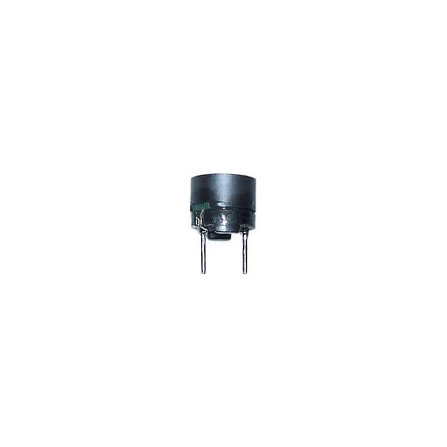
Regarding pin configuration and package, the CTSCH875DF-102K uses a radial through-hole format with two axial leads, typically spaced at 5.0 mm or 7.5 mm pitch. The leads are tinned copper, and the body is a rectangular or cylindrical ferrite core coated with a flame-retardant sleeve. The polarity is irrelevant for an inductor, but you must observe the lead orientation for proper mounting on a PCB: the leads are not symmetrical in terms of stress relief, so the component should be mounted with its body parallel to the board to minimize mechanical stress on the solder joints during vibration. The datasheet provides a recommended PCB hole diameter (usually 0.8–1.0 mm) and pad layout; using these prevents wicking issues and ensures reliable solder fillets. For high-vibration environments, consider adding a bead of conformal coating or an adhesive anchor under the body, as the radial leads are the only mechanical support.
Thermal management for this inductor is straightforward but often overlooked. The core and windings dissipate heat primarily through the lead frame and the outer surface. There is no dedicated thermal pad, so the component relies on convection and conduction through its leads. On a standard FR-4 PCB, the effective thermal resistance from the winding to ambient is typically 60–80°C/W. At a 0.2 A RMS current with a 10-ohm DCR, the copper loss is 0.4 W, causing a temperature rise of 24–32°C above ambient. If the ambient is 85°C, the winding temperature reaches 110–117°C, which is safe but near the limit for long-term reliability. Always place the inductor away from other heat sources like power resistors or MOSFETs, and if possible, leave a 2–3 mm gap around the body to allow airflow. For high-frequency ripple currents, also account for core losses, which appear as additional heat; the datasheet’s characteristic curves for impedance versus frequency will help estimate this.
Finally, interpreting the characteristic curves is essential for real-world use. The primary curves are: inductance versus DC bias current (showing a gradual decline then a sharp drop at saturation), impedance versus frequency (showing a peak at SRF), and temperature rise versus current. When reading the inductance versus bias curve, note that the x-axis is usually expressed as a percentage of rated current; a 10% drop at 0.2 A means the effective inductance at your operating point is 900 µH, which changes your filter corner frequency. The impedance versus frequency curve is a log-log plot: the inductive reactance rises linearly with frequency until near SRF, then it peaks and falls rapidly. Use this to verify that your switching frequency is at least a decade below SRF to avoid capacitive behavior. The temperature rise curve is typically a straight line on a log scale; extrapolate it to your actual RMS current to estimate the steady-state winding temperature, then compare that against the derating guidelines. By cross-referencing these three curves, you can select the appropriate operating point, derating factor, and thermal solution for your specific power topology.