18AWG Blue Hook-Up Wire: 100ft Application Guide
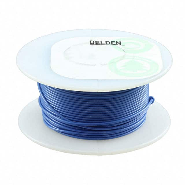
This application note addresses the practical integration of Belden’s 8501 006100, an 18 AWG stranded, blue, polyvinyl chloride (PVC) insulated hook-up wire, into electronic systems. Unlike printed circuit board traces, this wire is a discrete, flexible interconnect intended for point-to-point wiring, chassis grounds, power distribution, and signal routing within an enclosure or between boards. Its primary value lies in its high strand count (19/30) and 600V rated insulation, which provides excellent flexibility and robust dielectric strength for low-to-moderate current paths. When designing with this wire, you are not laying out copper on a laminate; you are creating a controlled, physical harness. The most effective circuit topology is a star or single-point ground arrangement, particularly for analog or mixed-signal sections. Run a dedicated 18 AWG blue wire from each sub-circuit’s ground reference back to a central chassis ground stud, avoiding daisy-chaining ground returns between high-current loads and sensitive signal stages. For power distribution, use the blue wire for the negative or return rail in a single-supply system, pairing it with a red or black wire for the positive rail; this color-coding convention minimizes assembly errors. Avoid using this wire for high-frequency RF (above 1 MHz) signal paths where controlled impedance is critical, as its geometry is not specified. Instead, reserve it for DC power, low-frequency analog signals (e.g., audio, sensor outputs below 100 kHz), and digital control lines (e.g., I2C, GPIO) where series termination or pull-up resistors are placed at the source or receiver end to damp ringing on longer runs.
When selecting supporting passives, the 18 AWG conductor has a nominal DC resistance of approximately 6.5 ohms per 1000 feet, so for a 100-foot spool, the total loop resistance is about 1.3 ohms (out and return). For a design drawing 1 ampere, this yields a 1.3V drop—unacceptable for most 3.3V or 5V logic. Therefore, always oversize the wire or reduce the load if voltage drop is a concern. For a 1A load over a 10-foot run (20-foot loop), the drop is 0.13V, which is tolerable. In practice, use this wire for loads up to 2.5A for short (<5 ft) runs, but derate to 1A for longer lengths. Place a bulk electrolytic capacitor (e.g., 100 µF to 470 µF, 25V) at the load end of the wire to decouple inductance, and a 0.1 µF ceramic capacitor directly at each IC’s power pin. If you are using the wire for a twisted pair (e.g., for differential signals), twist two lengths of the blue wire together—three to four twists per inch—to reduce common-mode pickup. For termination of digital lines, use a series resistor (33–100 Ω) at the driver, and for analog inputs, add a low-pass RC filter (e.g., 1 kΩ and 0.1 µF) at the ADC pin to reject noise.
PCB layout recommendations differ here because the wire connects to a PCB via a connector or solder terminal. Treat the wire as a transmission line extension of the PCB trace. At the PCB landing pad, use a strain-relief hole or a screw terminal rated for 18 AWG. Solder joints on the PCB should have a minimum pad diameter of 0.1 inches to allow for the stranded conductor’s flexibility. Route the wire away from sharp metal edges and heat sources. When routing inside a chassis, keep the blue wire at least 0.25 inches away from high-voltage AC lines or switching regulators. For critical analog signals, route the wire along the chassis ground plane, not floating in free space, to provide a defined return path. If the wire passes near a noisy transformer, use a ferrite bead clamped onto the wire (e.g., a snap-on core) to suppress common-mode noise. Do not run the wire parallel to AC mains wiring for more than 1 inch; cross at 90 degrees if necessary. For harness management, use lacing cord or spiral wrap to bundle wires, but do not bind the blue wire tightly with high-current switching wires—keep at least 0.5 inches separation to prevent capacitive coupling of switching transients.
For EMC/EMI, the wire itself is a radiator and an antenna. The PVC insulation provides no shielding, so you must rely on layout and filtering. To minimize radiated emissions, keep the return current path as close to the source wire as possible. If you have a blue wire carrying a PWM signal, twist it with its return ground wire. For shielded applications, use a separate shielded cable; this hook-up wire is not shielded. To mitigate conducted emissions, place a common-mode choke (e.g., 100 µH) at the PCB entry point for the wire pair. For electrostatic discharge (ESD) immunity, ensure the wire’s insulation does not touch exposed metal chassis edges without a grommet—abrasion can cut the PVC and cause shorts. If the wire carries a signal from a sensor outside the enclosure, add a TVS diode (e.g., SMAJ5.0A) to ground at the PCB connector. Also, ground the chassis at one single point to prevent ground loops that create magnetic field coupling into the wire loop area.
Common pitfalls include over-tightening the wire at a screw terminal, which can break the fine strands. Use a ferrule or tin the wire tip only if you are certain the connection will not be reworked; otherwise, use a proper ring terminal. Another pitfall is using the blue wire for AC mains (line voltage) inside a product—this wire is rated at 600V, but it is not dual-insulated for primary-side use without a protective sleeve. Avoid routing the wire near any sharp bend radius less than 10 times the wire diameter (0.1 inches), which can fracture the copper strands. Also, never use the blue wire as a fuse or current-sensing element; its resistance varies with temperature. When stripping the insulation, use a 18 AWG stripper, not a knife, to avoid nicking the strands.
For prototyping, use the blue wire for hand-wired breadboards and perfboards. Pre-cut lengths of 2, 4, and 6 inches for quick jumper connections. When bench testing, measure the voltage drop across the full length of wire at the intended load current using a four-wire Kelvin connection to verify you are within the design budget. Use a thermal camera to check for hot spots if the wire carries >2A continuously. For signal integrity testing, connect a function generator to one end and an oscilloscope probe to the other; observe any ringing or attenuation at your frequency of interest. Finally, perform a continuity check with a multimeter after assembly to ensure no strands are broken, and a hipot test (500V DC) between the blue wire and chassis ground to verify the insulation integrity. Always leave a service loop of extra wire at both ends to allow for re-termination during debugging.