Design Tutorial: ECG.0B.302.CYM Crimp Connector
Introduction: Why This Connector?
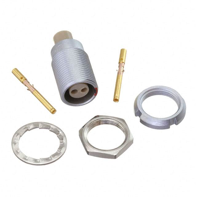
The LEMO ECG.0B.302.CYM is a 2-position, female, crimp-style, push-pull connector. It is not a generic header; it is a precision, self-latching, IP50-rated circular connector with a metal shell and a keying mechanism. For this tutorial, it is the perfect choice because it enforces a disciplined design approach: you must plan for its crimp tooling, its panel-mount footprint, and its current rating. This connector forces you to think about mechanical strain relief, polarity, and serviceability—things often ignored when using cheap pin headers. We will use it as the power input for a portable, battery-powered, 12V sensor node that draws up to 2A continuous.
Design Requirements and Specifications
The circuit is a DC-DC buck converter (from 12V to 5V) powering a Raspberry Pi Pico and a 5V/1A solenoid valve. The connector must handle the input side: 12V ±10%, 2A max continuous, with a 3A fuse for short-circuit protection. Key electrical specs for the ECG.0B.302.CYM: rated at 5A per contact (at 50°C), contact resistance ≤ 5 mΩ, and dielectric withstanding voltage of 1kV AC. Mechanically, we need a panel mount (front side) with a 0.9mm–1.2mm thick panel cutout of 8.0mm diameter. The crimp contacts accept 24–20 AWG wire (0.5–0.75 mm²).
Step-by-Step Design Process with Calculations
1. Thermal check: The connector’s 5A rating is at 50°C ambient. Our node runs in a 40°C enclosure. Derating: For every 10°C above 50°C, reduce by 10%. At 40°C, we are below the rating, so no derating needed. But we add a safety margin: 2A continuous is 40% of the 5A rating—excellent.
2. Voltage drop: With two contacts (V+ and GND) in series, total resistance = 2 × 5 mΩ = 10 mΩ. At 2A, voltage drop = 2A × 0.01Ω = 20mV. That’s negligible for a 12V rail. But we also add wire resistance: if we use 0.5mm² wire, 1 meter round trip has ~35 mΩ, giving 70mV drop. Still fine.
3. Fuse selection: A 3A fast-blow fuse protects the wiring. The connector’s 5A rating is above the fuse, so the connector will not fail before the fuse blows.
4. PCB footprint: The connector has a solder cup for the shell ground (if using a shielded version, but this is not shielded). We will use a separate chassis ground point. The male plug (not shown) will have a locking nut; we need a cutout in the enclosure.
5. EMI consideration: Since this is a buck converter, input ripple current flows through this connector. We add a 10µF ceramic and a 100µF electrolytic right at the connector pins inside the PCB to minimize inductance loop.
Component Selection Rationale for the Complete BOM
- Crimp contacts: LEMO part number FGG.0B.302.CYMD (male contacts) for the plug side, but for our receptacle we need the female crimp contacts: FFA.0B.302.CYMD. Use genuine LEMO crimp contacts, not clones—they have controlled hardness for the crimp die.
- Crimp tool: LEMO’s D.0B.300.DCP crimping pliers (or an equivalent M22520/2-01 with positioner). Do not use a generic crimper; the insulation grip and conductor crimp must be independent.
- Wire: 20 AWG high-strand-count silicone wire (for flexibility) rated at 200°C. Use two colors: red and black.
- Buck converter: TI TPS5430 (3A, 5V output). Input capacitor: 10µF 25V X7R + 100µF 25V electrolytic (Panasonic EEE-FK1E101P).
- Fuse holder: Inline blade fuse holder with a 3A ATO fuse.
- Panel: Aluminium enclosure, 2mm thick. Use a 8.0mm punch for the hole.
- Strain relief: A cable clamp on the internal side of the panel to prevent tension on the crimp contacts.
Simulation Tips and What to Look For
Simulate the buck converter in LTspice using the TPS5430 model. Add a lumped parasitic model of the connector as a series resistance of 10 mΩ and a parallel capacitance of 2pF (negligible). More importantly, simulate the input ripple current: look at the current waveform through the connector. You will see high di/dt spikes at the switching frequency (500kHz). The connector’s inductance (about 10nH) will cause voltage spikes of L·di/dt. With di/dt = 1A/ns, that’s 10V spikes—but that’s unrealistic; in practice, the PCB decoupling caps absorb this. In simulation, monitor the voltage across the connector pins—if it exceeds 100mV of ripple, increase input capacitance. Also simulate a 3A short circuit at the output to ensure the fuse blows before the connector heats.
Prototype Build and Testing Methodology
1. Crimp process: Strip 4mm of insulation. Insert wire into the crimp barrel. Use the crimp tool with the correct positioner. First, crimp the conductor (the front part), then crimp the insulation grip (the rear part). Pull test: the wire must not pull out with 5kg force.
2. Insertion: Insert the crimped contacts into the receptacle body from the rear. You will hear a click. Use the plastic extraction tool to remove if misaligned.
3. Panel mounting: Mount the receptacle from the front of the panel. Tighten the nut to 0.4 Nm—do not overtighten, as it will deform the gasket.
4. Wiring: Connect red to the positive input of the PCB, black to the ground plane. Add a ferrite bead (e.g., 600Ω at 100MHz) on the positive line right after the fuse to suppress high-frequency noise.
5. Test with dummy load: Before connecting the Pico, use a 2Ω, 25W resistor as a load to draw 2A at 5V (from the buck output). Measure the temperature rise of the connector’s metal shell with a thermocouple—after 1 hour, it should be less than 30°C above ambient.
6. Mating test: Plug and unplug the mating connector 100 times to ensure no intermittent contact. Measure voltage drop across the connector while wiggling the cable—should remain stable within ±1mV.
Performance Verification and Optimization
Use a 4-wire Kelvin measurement to measure the true contact resistance: apply 1A and measure the voltage across the connector pins. Expect ≤ 6 mΩ per contact. If higher, re-crimp. Measure the transient voltage drop when the solenoid valve switches on (inductive load): you should see less than 200mV dip on the 12V rail. If you see more, add a 100µF capacitor directly at the valve driver. For optimization, consider adding a second ground contact in parallel (if you use a 4-pin version) to halve resistance—but for this design, 2 pins are fine. Finally, run an IR camera on the connector during a 3A continuous load test for 10 minutes—the connector should stay below 60°C. If it runs hot, you likely have a bad crimp—re-do it. This connector rewards precision: a perfect crimp will outlast the equipment it powers.