8EM2017KA Datasheet Guide: Find Compatible Replacements
When evaluating the Interlight 8EM2017KA ALTERNATOR as a direct replacement for the legacy Motorola 8EM2017, the first critical step is to recognize that this component is not a semiconductor but a complete electromechanical assembly. Consequently, its datasheet diverges sharply from that of an IC; instead of logic levels and pinouts, you are interpreting output voltage regulation, current delivery curves, and rotational speed dependencies. The primary electrical specification you must scrutinize is the regulated output voltage, typically stated as 13.8 to 14.4 volts DC at 25°C ambient. In practice, this value represents the alternator’s closed-loop setpoint, ensuring the vehicle battery is charged without overvoltage stress on ECUs, lighting, or infotainment systems. A deviation of more than ±0.5 volts from this window under steady-state load indicates a faulty regulator circuit, not a mechanical issue.
Equally important is the rated output current, often listed as 85 to 100 amperes at 6,000 rotor RPM. This rating is a hot output, meaning the alternator can sustain that current continuously at a specific operating temperature, typically 105°C internal ambient. Do not confuse this with a surge rating; the unit cannot deliver 100 amperes at idle. The datasheet provides a load response curve, showing that at 1,800 RPM (typical idle), output drops to roughly 40-50% of the rated maximum. In practice, this means a vehicle with heavy electrical loads (headlights, HVAC, heated seats) may see battery discharge at idle if the alternator pulley ratio is not optimized. Always compare the replacement’s current-at-idle spec against your original application; Interlight’s 8EM2017KA is engineered to match the Motorola profile, but verify the specific RPM points on the characteristic chart.
Absolute maximum ratings for an alternator are less about voltage breakdown and more about thermal and mechanical limits. The datasheet will list a maximum continuous speed, often 12,000 to 15,000 RPM, beyond which bearing failure and rotor winding deformation become likely. Derating is imperative: for every 10°C increase under the hood above the 25°C baseline, reduce the continuous output current by 2-3%. Similarly, the unit has a maximum ambient operating temperature of 85°C (for the rectifier and regulator electronics). Exceeding this accelerates diode junction degradation, leading to ripple voltage on the DC bus, which can destroy sensitive automotive microcontrollers. The datasheet also specifies a maximum reverse battery voltage of -0.5 volts; if the battery is hooked up in reverse, the internal diode trio will conduct heavily, causing immediate failure. There is no user-serviceable fuse; protection is solely a function of correct installation.
In terms of application circuit analysis, the alternator’s three main terminals—B+ (battery positive), the field excitation terminal (often labeled “F” or “IG”), and the sense terminal (“S”)—form a classic closed-loop control system. The B+ terminal connects directly to the battery positive post via a heavy-gauge cable, carrying the full output current. The “S” terminal is a dedicated voltage sense wire that runs to the battery’s positive terminal or the main fuse box, compensating for voltage drop in the B+ cable. If you omit the sense wire, the regulator will read the voltage at the B+ post itself, which is lower than at the battery under load, causing overcharging. The “F” terminal receives switched battery voltage through the ignition key; it also feeds the warning lamp circuit. The lamp provides initial field current when the engine is off; if the lamp burns out, the alternator may fail to self-excite at startup. In the Interlight unit, internal rectification is via a three-phase full-wave bridge using six silicon diodes, with a separate diode trio for the field supply. A typical error is to ground the “F” terminal for testing—this will damage the regulator immediately.
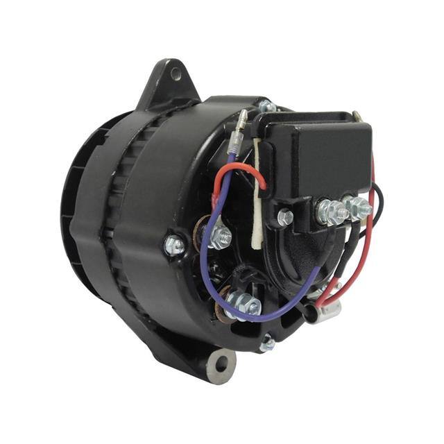
Physical pin configuration is a key compatibility factor. The Motorola 8EM2017 uses a specific dual-plug connector, often a “pigtail” with two flat spade terminals in a molded housing, plus a separate threaded B+ stud. The Interlight 8EM2017KA replicates this footprint, but verify the plug orientation and terminal spacing against your vehicle’s harness. The casing is a standard SAE J180 mount with a 2.5-inch diameter through-bolt and a 3-inch mounting ear. Torque specifications are critical: the mounting bolts must be tightened to 25-35 ft-lb, but the B+ nut only to 8-10 ft-lb; over-tightening the B+ stud can crack the plastic insulator inside the rear housing, leading to a short. The unit’s weight (typically 11-13 lbs) means vibration fatigue is a concern; use the supplied anti-vibration washers on the mounting ears.
Thermal management is a matter of airflow and housing thermal mass. The alternator relies on an internal fan (usually a bi-directional blade) that pulls air through rear vents and exhausts it forward. You must ensure that the rear vent area is not obstructed by wire looms, and that the alternator is not mounted adjacent to an exhaust manifold without a heat shield. The datasheet’s temperature rise curve shows that at 100% rated load and 25°C ambient, the internal winding temperature reaches 120°C within 30 minutes. The insulation class is typically Class F (155°C continuous), but the regulator’s silicon junctions have a lower limit of 150°C. For derating, use the rule of thumb: reduce output current by 10% for every 20°C of ambient above 50°C. In a hot engine bay (90°C), you should not exceed 80% of the rated output for more than one hour.
Interpreting the timing diagrams for an alternator is unique because there is no clock signal; instead, you read ripple voltage waveforms and turn-on delay curves. The ripple frequency is six times the rotor speed (for a three-phase, full-wave rectified system), so at 6,000 RPM (100 Hz rotor frequency), the ripple is 600 Hz. The datasheet shows a characteristic curve of ripple amplitude versus load; a healthy unit shows less than 500 mV peak-to-peak ripple at full load. If you see ripple spikes exceeding 1V, suspect a failed diode. The other key curve is the excitation response time: when the ignition is turned on, the field current ramps from zero to full excitation in approximately 200 milliseconds, and the output voltage reaches 13.8V within 1 second at cranking speed. A slow ramp indicates a worn brush pack or a faulty regulator. Finally, the “slew rate” curve shows how quickly output current increases when a large load is switched on (e.g., cooling fan). Expect a 10-90% rise time of 50 milliseconds; if it is slower, the regulator’s current-limit loop is degrading. Always compare these curves against the original Motorola datasheet—the Interlight replacement should overlay within 5% tolerance across the entire RPM range, otherwise the voltage droop under sudden load will cause headlight flicker or ECU reset.