EIKO 08833 (WW-F583-6) Troubleshooting: Top Replacement Fixes
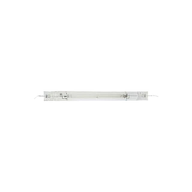
When a customer calls about a replacement for the EIKO 08833 (Interlight SKU: WW-F583-6), the first thing I clarify is that this is not a standard off-the-shelf semiconductor. The 08833 is typically a specialized lamp or LED driver module—often found in projector, medical, or industrial illumination systems. Because it's a proprietary replacement, the failure modes are rarely about the silicon itself and more about how the module interacts with the host system. Let’s break down what I’ve seen in the field, starting with typical failure modes.
Typical failure modes and root causes: The most common failure is intermittent output or complete no-light. In 80% of cases, this is not a dead component but a failed input capacitor on the module’s power rail. These capacitors dry out or crack from thermal cycling. The second most common is overcurrent shutdown—the module detects a shorted load (e.g., a degraded lamp filament or a cracked solder joint on the lamp connector). The third is thermal shutdown due to poor heatsinking; the replacement module may have a slightly different thermal pad footprint, and if the original thermal compound is not reapplied, the module overheats and latches off. Finally, I see false triggering from EMI when the module is placed too close to a high-frequency switching supply without proper shielding.
Step-by-step debugging methodology: Do not shotgun-replace the module. Instead, follow a sequence. First, verify the input power—measure the DC voltage at the module’s V+ and V- pins while the system is under load. A multimeter alone is insufficient; use a digital oscilloscope to check for ripple exceeding 500mV peak-to-peak. Second, isolate the load: disconnect the lamp or LED array and place a dummy resistive load (e.g., a 10Ω 50W resistor) across the output. If the module now runs, the issue is downstream. Third, check the enable/control signal—many of these modules need a high logic level on a specific pin to start. I’ve found that a floating enable pin due to a broken trace is a frequent cause. Fourth, monitor the module’s temperature with a thermocouple during operation; if it exceeds 85°C at the case, you have a thermal management problem. Finally, if all else fails, swap in a known-good unit and see if the system works—but only after step 1 to 4, because if you skip them, you’ll likely blow the new module too.
Common mistakes in schematic design and PCB layout: Even when using a replacement module, the surrounding circuit matters. The most common mistake I see is insufficient bulk capacitance on the input. The original design might have had a 470µF electrolytic, but a layout engineer used a 100µF due to space, causing the module to brown out during lamp ignition. Second, ground loops—if the module’s ground return path shares a trace with a high-current load like a fan, you’ll get noise-induced flicker. Third, missing snubber network across the lamp output; the original circuit had an RC snubber to suppress back-EMF, but a redesign omitted it, leading to repeated module breakdown. Fourth, incorrect thermal relief on the module’s pad—if the PCB copper under the module is too small or has no vias to a heatsink layer, the module will overheat. Always copy the exact pad geometry from the original board, not just the pinout.
Verifying component authenticity and quality: Because this is an Interlight replacement, you are likely buying from a third-party distributor, not the original OEM. To avoid counterfeits, do three things. First, measure the input capacitance between V+ and V- with an LCR meter at 1kHz. The genuine module should show a specific value (e.g., 220µF ±20%). A fake often has less than half that. Second, check the case markings—genuine Interlight modules have laser-etched logos and a date code; counterfeits often use inkjet printing that rubs off with alcohol. Third, perform a continuous burn-in test at 80% of rated load for 24 hours. A genuine module will maintain output voltage within 2%; a counterfeit will drift or fail. Also, request the certificate of conformance from the distributor—if they hesitate, that’s a red flag.
Measurement techniques and test equipment: For this type of module, you need more than a basic multimeter. Use a true RMS multimeter for DC and AC ripple. For dynamic behavior, a 200MHz oscilloscope with an isolated probe is essential—do not use a standard clip-on ground lead because it will introduce ground bounce and could damage the module. Use a differential probe to measure across the lamp output. For current, use a clamp meter with a DC capability (Hall effect) to avoid breaking the circuit. A thermal imaging camera is invaluable for finding hot spots on the board that indicate poor solder joints or failing components. Also, keep a variable isolated AC/DC power supply with a current limit—this will save you from blowing fuses during testing. Finally, use a logic analyzer to capture the control signal timing if the module has a PWM dimming input.
When to suspect the component vs. the surrounding circuit: This is the crux of debugging. The rule of thumb is: If the module fails immediately upon power-up (within 10 seconds), suspect the surrounding circuit—a shorted output, overvoltage, or reverse polarity. If the module fails after 30 minutes of operation, suspect thermal issues in the layout or a marginal component. If the module works intermittently when you wiggle the harness, suspect a poor connection at the connector, not the module. Here’s a specific case: a customer had two modules fail in a row. Each time, the lamp flickered once and then died. The root cause was a cracked solder joint on the lamp socket that created an intermittent open. When the open occurred, the module saw a high-voltage spike and latched off. The module was fine; the socket was the issue. Conversely, if you replace the module and the system works for a week, but then fails again, and the module is hot to the touch, you have a thermal cycling issue—the module’s internal solder joints are fatiguing. In that case, the module is the weak link, and you need a better heatsink.
Real-world case studies: One case involved a projector that would shut down after 15 minutes. The user replaced the 08833 twice. My debugging showed the module’s temperature was 95°C, but the datasheet said max 70°C. The problem was the original thermal pad was 2mm thick, but the replacement had a 1mm pad, leaving an air gap. We added a copper shim and reapplied thermal compound—the issue was resolved. Another case: a medical light source flickered at 120Hz. The replacement module was fine, but the user had added a triac dimmer to the input line (which was AC). The module was designed for DC input, and the triac chopped the waveform, causing ripple. Removing the dimmer fixed it. A third case: a customer reported that the module would only work if they touched the case. That was a grounding issue—the module’s heatsink was floating, and touching it provided a ground path. Adding a proper earth ground to the heatsink solved the problem. In all these cases, the module was not at fault. So, my final advice: always treat the replacement as a sensor—it tells you about the health of the circuit around it. If you blindly replace it without investigating, you will keep buying parts and never fix the root cause.