Design Tutorial: CBL CIRC 7POS Male 1.64' (2387114-1)
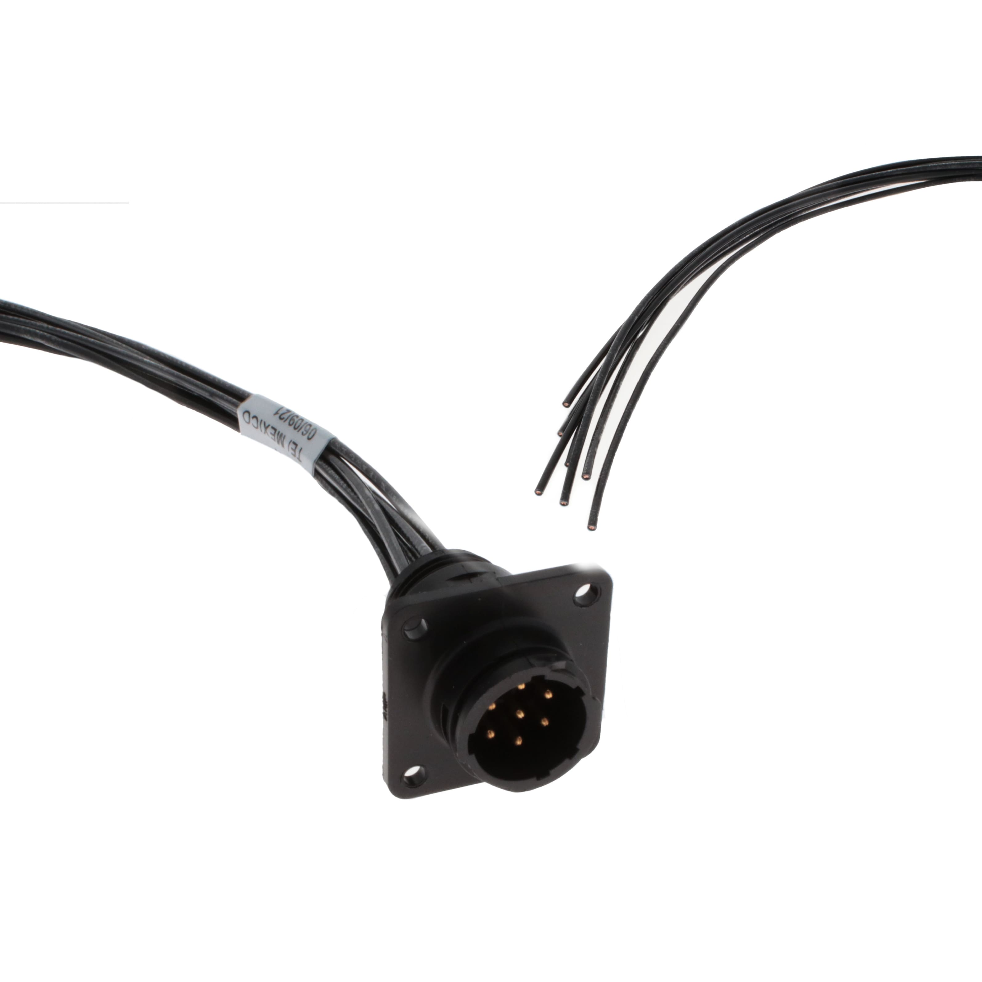
When you need a compact, reliable interface between a sensor suite and a microcontroller, the TE Connectivity AMP Connectors 2387114-1 cable assembly is a practical starting point. This part is a 7-position male cable assembly with a 1.64-foot (500 mm) length. It uses a 1.5 mm pitch, wire-to-board connector system with a positive latch, which makes it suitable for vibration-prone environments like robotics or handheld instruments. The pre-crimped leads and overmolded strain relief remove the need for a separate crimping tool and reduce assembly time. For a tutorial, this component is ideal because it forces you to think about pinout, current derating, and signal integrity over a short but flexible harness.
Design requirements and specifications. We will build a 7-channel analog sensor breakout for a 3.3 V microcontroller. Each channel carries a 0-3.3 V signal from a potentiometer or resistive sensor. The cable must also supply 3.3 V and ground to the sensor board. The total current budget is 150 mA maximum, with each signal line limited to 10 mA. The ambient temperature range is 0 °C to 70 °C. The connector’s rated voltage is 50 V AC/DC, and its current rating per contact is 2 A, so we have ample margin. The key constraint is crosstalk and ground return: with only 7 positions, we must allocate one pin to ground and one to power, leaving five analog channels. We will use a star ground at the sensor board to minimize noise.
Step-by-step design process. First, assign the pinout. Pin 1: 3.3 V. Pin 2: ground. Pins 3-7: analog channels A0-A4. This keeps power and ground adjacent, reducing loop area. Second, calculate the voltage drop on the power line. The cable uses 26 AWG wire, which has a resistance of approximately 0.133 ohms per meter. For a 0.5 m length, the round-trip resistance is 0.133 ohms. At 150 mA, the drop is V = I × R = 0.15 × 0.133 = 0.02 V, or 20 mV. This is negligible for a 3.3 V rail, but if you daisy-chain multiple boards, recalculate. Third, verify current per contact. Each analog line carries at most 10 mA, well below the 2 A rating. Fourth, consider crosstalk. With a 1.5 mm pitch and no individual shielding, keep analog signal traces on the sensor board short and add a 100 nF capacitor from each analog pin to ground. The cable’s twisted-pair construction is not present here, so expect about 5-10 mV of coupling at 10 kHz. For DC or low-frequency sensors, this is acceptable.
Component selection rationale. The complete BOM includes the 2387114-1 cable assembly, a 7-position female receptacle (TE 2387115-1 or equivalent) for the sensor board, and a 7-position male header for the microcontroller board. Use a 0.1 µF X7R ceramic capacitor per analog channel for decoupling. Add a 10 µF tantalum capacitor across the 3.3 V and ground pins at the sensor board to handle transient currents. For the analog sensors, choose 10 kΩ potentiometers or 10 kΩ NTC thermistors with a 10 kΩ series resistor to form a voltage divider. The 10 kΩ value keeps current at 0.33 mA per channel, well under the 10 mA limit. The cable’s male pins mate with the female receptacle, and the latch prevents accidental disconnection.
Simulation tips. In LTspice or KiCad, model the cable as a lumped resistance of 0.133 ohms per line and a capacitance of 50 pF between adjacent lines. Run a transient simulation with a 1 kHz square wave on one channel and measure the voltage on an adjacent channel. You should see less than 10 mV of coupling. Also simulate the power rail with a 150 mA load step and verify that the 10 µF capacitor keeps the ripple below 50 mV. Look for ringing on the analog lines; if present, add a 100 ohm series resistor at the sensor output. The goal is to confirm that the 7-position cable does not introduce excessive noise or voltage drop.
Prototype build and testing methodology. Solder the female receptacle to a small perfboard or custom PCB. Connect the potentiometers as voltage dividers with the wiper going to the analog pins. Plug the 2387114-1 cable into the receptacle. On the microcontroller side, connect the male header to the ADC pins. Power up with a bench supply set to 3.3 V and current limit to 200 mA. Measure the voltage at the sensor board’s power pin; it should be within 30 mV of 3.3 V. Next, sweep each potentiometer from 0 to 100% and record the ADC values. They should span 0 to 1023 for a 10-bit ADC. Check for cross-talk by holding one channel at mid-scale and toggling an adjacent channel; the variation should be less than 2 LSB. Finally, flex the cable repeatedly and verify that the latch holds and no intermittent connections appear.
Performance verification and optimization. After the basic test, measure the noise floor with all inputs grounded. The RMS noise should be below 1 LSB. If not, add a 0.1 µF capacitor directly at the ADC input pin. For better accuracy, average 16 samples in firmware. To reduce crosstalk further, route the ground pin between the most sensitive analog channels if your pinout allows. The 2387114-1’s 1.64-foot length is short enough that transmission line effects are negligible below 1 MHz. For optimization, consider replacing the 10 kΩ potentiometers with 1 kΩ units to lower thermal noise, but verify that the current stays within the sensor’s capability. With these steps, your 7-channel sensor interface will be robust, repeatable, and ready for field use.