Troubleshooting INSERT FEMALE 10POS+1GND CRIMP 09330102702
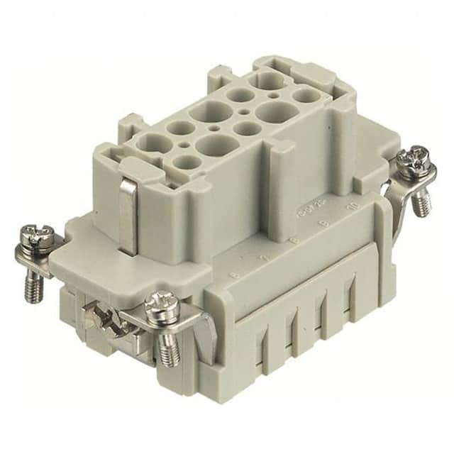
When a HARTING 09330102702 (10-position + ground female crimp connector) starts causing trouble, the odds are it is not the connector itself. This is a rugged, well-specified part. Most failures I see in the field trace back to crimping, mating, or layout. Let's walk through how to isolate them.
Typical failure modes and root causes. The three most common failures are intermittent opens, high-resistance contacts, and mechanical damage. Intermittent opens usually come from a poorly crimped contact that looked fine under a quick visual check. The wire strands may be nicked, or the conductor is not fully seated in the crimp barrel. High-resistance contacts often result from contamination, oxidation, or a mismatched crimp tool that crushed the contact instead of forming it. Mechanical damage typically shows up as a cracked housing or bent retention fingers after repeated mating cycles, especially when someone yanks on the cable instead of releasing the latch. The ground position is also a frequent troublemaker. Because it is a separate position, techs sometimes forget to crimp it, or they land a signal wire there by mistake.
Step-by-step debugging methodology. Start at the system level. Disconnect power and do a continuity check from the PCB pad to the far end of the harness. Wiggle the wire at the crimp while measuring. A reading that jumps from 0.2 ohms to open tells you the crimp is bad. Next, mate the connector and do a voltage-drop test under load. If you see more than 50 mV across a mated pair at rated current, pull the connector and inspect for fretting corrosion or a partially seated contact. If the problem follows the connector when you swap harnesses, the issue is in the connector. If it stays with the board, look at the mating header or the solder joints.
Common mistakes in schematic design and PCB layout. The biggest schematic error is treating the ground position as just another signal pin. It is not. It should tie directly to the chassis or power ground with a low-impedance path. I have seen designs where the ground pin routed through a thin trace and a ferrite bead, causing ground bounce that made the whole system flaky. On the layout side, the most frequent mistake is placing the mating header too close to tall components. The HARTING housing needs clearance for the latch and for the cable bundle to exit without side load. If the cable is forced into a tight bend right at the connector, the crimp area takes the stress and eventually cracks. Also, do not run high-current traces under the connector body. Heat from those traces can soften the plastic and reduce retention force.
Verifying authenticity and quality. Counterfeit HARTING connectors exist, especially on secondary markets. Check the laser marking on the housing. Genuine parts have crisp, consistent text with the HARTING logo and the part number. The plastic should feel rigid and slightly textured, not slick or chalky. Inspect the crimp contacts under magnification. Genuine contacts have uniform plating and a clean seam. Look at the packaging. HARTING ships these in branded bags or trays with a label that includes the SKU and batch code. If the price is 40 percent below distribution, be suspicious. Measure the contact retention force with a pull test gauge. A good contact should hold at least 40 N. If it pulls out with a light tug, it is either counterfeit or the wrong contact for the housing.
Measurement techniques and test equipment. Use a four-wire milliohm meter for contact resistance. A standard two-wire DMM will include lead resistance and can miss a marginal crimp. For intermittent faults, use a data logger or a scope in roll mode to catch glitches while you flex the harness. A thermal camera is invaluable. Under load, a bad crimp or a contaminated contact will show a hot spot within seconds. For insertion and withdrawal force, use a force gauge with a motorized stand. The spec for this connector is typically around 20 N per contact, so a full 11-position mate should feel consistent, not gritty or overly loose.
When to suspect the component versus the surrounding circuit. Suspect the connector when the fault moves with the harness, when a known-good harness fixes the problem, or when you see physical damage like cracked plastic or discolored contacts. Suspect the circuit when the fault stays on the same board regardless of which harness you use, or when multiple connectors on the same board fail at once. That pattern points to a layout issue, a power sequencing problem, or a soldering defect on the mating header.
Real-world case studies. A customer had a robot arm that would randomly fault during fast moves. The connector looked perfect. We flexed the harness while monitoring resistance and found one position jumping from 0.3 ohms to 12 ohms. The crimp had been made with the wrong die, which cut two strands and left the rest loose. Re-crimping with the HARTING tool fixed it. In another case, a medical device failed EMC testing. The ground position on the 09330102702 was tied to signal ground through a long, thin trace. We moved it to a direct chassis connection with a short, wide trace, and the emissions dropped by 12 dB. A third case involved a counterfeit batch. The contacts were undersized and would not lock into the housing. After a pull test showed only 15 N retention, the customer switched to authorized distribution and the problem disappeared. The lesson is simple: verify the crimp, verify the ground, and verify the source.