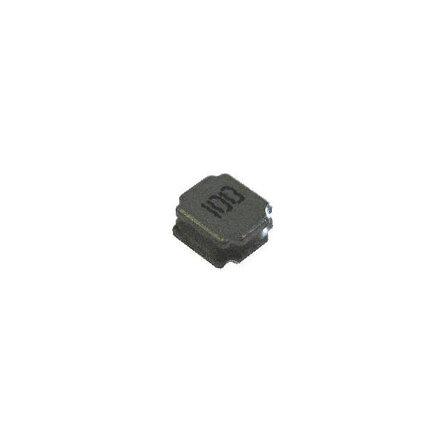
33UH SMD Power Inductor CTLVC5020F-330N: Application Note Guide
The Central Technologies CTLVC5020F-330N is a 33 µH shielded surface-mount power inductor with a nominal saturation current suitable for medium-power DC-DC conversion. It is most at home in non-isolated switching regulators, particularly step-down (buck) converters operating in continuous conduction mode at switching frequencies between roughly 200 kHz and 1.5 MHz. It also performs well in boost and single-ended primary-inductance converter (SEPIC) topologies where the inductor sees a defined DC bias plus ripple. Avoid using it in isolated flyback designs unless you have verified the peak current and thermal rise, because flyback leakage inductance and peak currents tend to exceed this part's comfortable operating window. For best results, target a ripple current of 30–40% of the DC output current; this balances core loss against output capacitance and transient response. If your ripple exceeds 50%, consider a lower-inductance part or a higher switching frequency rather than pushing the CTLVC5020F-330N into saturation.
Supporting passives determine whether the inductor actually delivers its rated performance. Choose input and output capacitors with low ESR and sufficient RMS current rating; polymer or ceramic capacitors in parallel with a bulk electrolytic work well. For the output, size capacitance so that the capacitive ripple is smaller than the inductor ripple contribution, and verify the capacitor's voltage derating—X5R and X7R ceramics lose significant capacitance under DC bias. The catch diode in an asynchronous buck must be a Schottky with reverse voltage at least 1.5× the maximum input voltage and a forward current rating above the peak inductor current. In synchronous designs, select MOSFETs with low gate charge and RDS(on); the low-side FET carries the inductor current during the off-time, so its conduction loss is a direct thermal path. Feedback resistors should be 1% or better, and the compensation network must account for the inductor's ESR zero—if you use a low-ESR output capacitor, add a small series resistor or type-II compensation to keep the loop stable.
PCB layout is where many designs lose efficiency and gain EMI. Place the inductor as close as possible to the switch node and the output capacitor, keeping the high-di/dt loop—input capacitor, high-side FET, inductor, and ground return—as tight as possible. Use a solid ground plane directly under the component, and connect the inductor's pads with short, wide traces; 2 oz copper is preferred for currents above 2 A. Do not route sensitive analog traces, feedback dividers, or compensation networks under or near the inductor, because the magnetic field extends beyond the shield. Keep the switch node copper area small to reduce capacitive coupling, but large enough to handle the current without excessive temperature rise. Thermal vias under the inductor pads help conduct heat into inner layers, but they must be tented or plugged to prevent solder wicking during reflow.
EMC performance depends on controlling both differential and common-mode noise. The shielded construction of the CTLVC5020F-330N reduces radiated H-field emissions, but the switching node still radiates E-field. Add a small RC snubber across the switch node or across the catch diode if you observe ringing above 100 MHz. For conducted emissions, a π-filter on the input—ceramic capacitor, ferrite bead or small inductor, and another ceramic capacitor—attenuates the high-frequency current drawn by the converter. Keep the input filter's ground return separate from the power ground and connect them at a single point. If your design must meet CISPR 25 or similar automotive standards, consider a shielded enclosure or a spread-spectrum clock on the controller. Always measure both peak and average emissions with the inductor loaded to its worst-case current, because core saturation changes the ripple waveform and therefore the harmonic content.
Common pitfalls include ignoring the DC bias effect on inductance, underestimating the saturation current, and assuming the shield eliminates all coupling. The CTLVC5020F-330N's inductance drops as DC current rises; verify the effective inductance at your operating point, not just the zero-bias value. Many engineers also forget that the inductor's self-resonant frequency limits its usefulness at high frequencies—if your switching frequency is above roughly 10 MHz, this part is not appropriate. Another frequent error is placing the inductor too close to a sensitive op-amp or ADC; even a shielded inductor leaks a small field, so keep at least 5 mm separation and orient the part so its axis is perpendicular to the sensitive trace. Finally, do not neglect thermal derating: the rated current is often specified at a 40 °C rise, so in a 70 °C ambient you may need to reduce current by 20–30%.
For prototyping, start with a known-good reference layout from the controller datasheet and substitute the CTLVC5020F-330N only after verifying pin compatibility and pad geometry. Solder the part with a reflow profile that peaks at 245–260 °C; hand soldering with a fine tip is acceptable for bench work but can crack the core if you apply mechanical stress. On the bench, measure inductor current with a current probe or a small series sense resistor—do not rely on the controller's internal current-sense signal alone. Check the ripple waveform for signs of saturation: a sudden increase in slope or a spike at the switch transition indicates the core is approaching saturation. Run the converter at full load, minimum input voltage, and maximum ambient temperature simultaneously; this is the worst-case corner. Use a thermal camera or thermocouple to confirm the inductor body stays below its rated temperature, and repeat the EMI scan after any layout change. If you see excessive ringing or efficiency loss, adjust the snubber or gate resistor before changing the inductor value.