Troubleshooting the DF40TC 30-Position 0.4mm SMD Connector
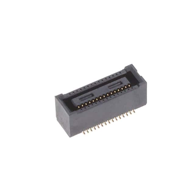
The Hirose DF40TC(3.0)-30DS-0.4V(58) is a 30-position, 0.4mm pitch board-to-board receptacle with a 3.0mm stack height. It is widely used in compact modules such as camera assemblies, display drivers, and RF boards. Because the pitch is 0.4mm and the mated height is tight, most field failures trace back to mechanical stress, soldering quality, or footprint accuracy rather than the connector itself.
Typical failure modes and root causes. The most common issue is intermittent contact on one or more positions. Root causes include solder bridging between adjacent pins, incomplete reflow on the receptacle pads, flux residue creating leakage, or mechanical misalignment during mating. A second failure mode is a cracked solder joint at the receptacle, usually caused by board flexing or by uneven mating force. Third, bent or pushed-in contacts occur when the mating plug is inserted at an angle or when the board-to-board alignment is off by more than the connector’s self-alignment range. Finally, contamination from no-clean flux or handling oils can cause high-resistance opens that only appear after thermal cycling.
Step-by-step debugging methodology. Start with a visual inspection under 10x to 20x magnification. Look for solder bridges, missing solder, or lifted pads. Next, check mechanical alignment: the plug and receptacle should mate with a soft click and sit flush. If the system is intermittent, flex the board gently while monitoring a known signal. Then perform continuity checks from the receptacle pad to a test point on the same net. If continuity is good but the signal fails, the problem is likely in the surrounding circuit, not the connector. For intermittent opens, use a data logger or oscilloscope in roll mode to capture the event while tapping or flexing the assembly. Finally, reflow one connector at a time using a hot-air station with controlled temperature to isolate whether the issue is solder-related.
Common mistakes in schematic design and PCB layout. Designers often forget that the DF40TC series requires a specific mating plug and a defined stack height. Using a plug from a different DF40 variant can cause poor contact force. On the PCB, the most frequent error is an incorrect footprint: pad length, width, or spacing that is slightly off. Even 0.05mm error can cause tombstoning or bridging. Another mistake is routing traces between the pads without solder mask dams, which increases bridging risk. Also, placing vias directly in the pad or too close to the pad can wick solder away during reflow. Finally, failing to provide adequate mechanical support or alignment pins can lead to mating misalignment and contact damage.
How to verify component authenticity and quality. Purchase only from authorized distributors. Counterfeit DF40TC connectors often have inconsistent plating, rough plastic, or missing brand markings. Inspect the reel label: Hirose uses a specific format with lot and date codes. Check the connector body for the Hirose logo and the exact part number. Under magnification, genuine contacts have uniform gold plating and smooth edges. Measure the pitch with a calibrated optical comparator; 0.4mm pitch should be consistent across all 30 positions. If the connector feels loose or the contacts do not retain the plug, suspect a counterfeit or a damaged lot.
Measurement techniques and test equipment. Use a digital multimeter with a fine-tip probe for continuity, but be aware that probe pressure can temporarily fix an intermittent joint. For low-resistance measurements, use a 4-wire Kelvin setup to avoid lead resistance. An oscilloscope with a high-impedance probe can monitor signal integrity during vibration. For solder joint quality, use X-ray inspection for bridges and voids. A thermal camera can reveal hot spots from high-resistance connections. For mechanical verification, use a force gauge to measure mating and unmating forces; the DF40TC series typically requires 0.5N to 1.5N per contact pair. Finally, a time-domain reflectometer (TDR) can locate impedance discontinuities caused by a damaged connector.
When to suspect the component vs. the surrounding circuit. If multiple adjacent positions fail, suspect the connector or soldering. If only one signal fails and the connector passes continuity, suspect the circuit. If the failure moves when you flex the board, suspect mechanical stress on the connector or solder joints. If the failure appears only after temperature cycling, suspect contamination or a marginal solder joint. If the connector is new and from a questionable source, suspect authenticity. As a rule, replace the connector only after you have verified the footprint, reflow profile, and mating alignment.
Real-world case studies. In one case, a camera module using this connector had random image dropouts. Visual inspection showed no bridges, but X-ray revealed a void in one ground pad. Reflow profile adjustment eliminated the void. In another case, a customer reported intermittent power to a display. The root cause was a 0.1mm misalignment in the PCB footprint, causing the plug to push one contact out of place. Redesigning the footprint with proper alignment pins solved it. A third case involved a counterfeit connector that failed after 50 mating cycles. The gold plating was only 0.1µm instead of the specified 0.3µm. Switching to an authorized distributor resolved the field returns. Finally, a design that routed a signal trace between two receptacle pads caused a solder bridge during assembly. Adding solder mask dams and moving the trace to an inner layer eliminated the defect.