BEZEL 90-Degree Beam Deflector (30663): Application Note Guide
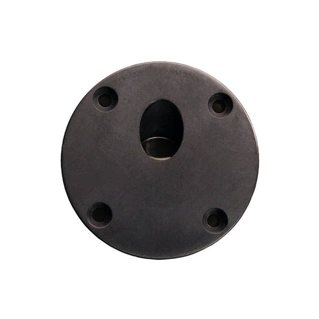
The Excelitas Technologies 30663 90-degree beam deflector bezel is a precision optical mounting component designed to redirect an incident beam path by 90 degrees while maintaining mechanical registration with the host optical assembly. Although it is a passive mechanical part, its integration into a photonic or electro-optical system demands the same care you would apply to an active device, because misalignment, contamination, or thermal drift of the deflector directly degrades signal-to-noise ratio, coupling efficiency, and measurement repeatability. The 30663 is typically used with photodiodes, avalanche photodiodes, or small form-factor laser modules where the beam must be folded to fit a compact enclosure. Treat it as a critical optical interface rather than a simple bracket.
Recommended circuit topologies are less about the bezel itself and more about the transimpedance or biasing network that follows the deflected beam. For photodiode-based receivers, use a transimpedance amplifier (TIA) with a feedback resistor chosen so the RC time constant supports your required bandwidth while keeping the noise gain low. Place the photodiode as close as physically possible to the 30663 exit aperture to minimize beam divergence between the deflector and the active area. For laser sources, drive the emitter with a low-noise current source or a laser diode driver that includes soft-start and reverse-bias protection, since the folded beam path often means the emitter is mounted on a separate sub-board. In both cases, keep the optical axis orthogonal to the bezel mounting face within the manufacturer's specified angular tolerance, typically better than 0.5 degrees for precision variants.
Supporting passive selection should prioritize stability over absolute value. Use thin-film or NP0/C0G ceramic capacitors in the TIA feedback and supply decoupling paths, because their low voltage coefficient and low dielectric absorption preserve pulse fidelity after the beam is folded. For the photodiode bias network, select resistors with tight temperature coefficients (25 ppm/°C or better) to prevent responsivity drift as the bezel and its mount reach thermal equilibrium. If the 30663 is used in a temperature-cycled environment, avoid electrolytic capacitors anywhere near the optical path; their electrolyte can outgas and deposit a haze on the deflector surface. Inductors, if used for bias tees, should be shielded to prevent magnetic coupling into the high-impedance photodiode node.
PCB layout for the 30663 assembly must respect both electrical and optical constraints. Mount the bezel on a rigid, flat surface, preferably a machined aluminum or FR4 plate with a ground plane directly beneath the photodiode or emitter. Route the photodiode anode trace as a short, guarded run to the TIA input, keeping the trace on a single layer and surrounded by a ground pour tied to the analog ground. Do not route digital or switching signals under the bezel footprint, as capacitive coupling into the optical receiver can inject noise that is difficult to distinguish from the optical signal. If the bezel must be mounted to a PCB, use threaded inserts or through-hole standoffs rather than relying on adhesive alone, and provide clearance holes so the mounting hardware does not stress the board. Keep the optical axis free of solder mask and silkscreen within a 5 mm radius of the aperture to avoid stray reflections.
EMC and EMI considerations are dominated by the fact that the folded beam path often brings the optical detector into proximity with switching regulators, clock lines, or motor drivers. The 30663 itself is metallic and can act as a small antenna if it is not bonded to chassis ground. Ground the bezel body to the enclosure or to a dedicated shield plane using a short, wide strap or a conductive gasket. Place a ferrite bead or a small RC filter on the photodiode bias line if the supply is shared with digital circuitry. For laser driver applications, keep the return current path directly under the drive trace and avoid loops that enclose the bezel aperture. If the system must meet CISPR or FCC limits, test with the bezel installed, because its presence changes the near-field coupling pattern.
Common pitfalls include over-torquing the mounting screws, which can warp the bezel and shift the 90-degree angle; leaving the protective window film in place during optical alignment; and using opaque potting compound that creeps into the beam path. Another frequent error is assuming the deflector is polarization-insensitive when some coated variants are not; verify the coating specification against your source polarization. Finally, do not clean the deflector with acetone or alcohol unless the manufacturer confirms compatibility, as some coatings are damaged by solvents.
For prototyping, mount the 30663 on a kinematic or at least a slotted bracket so you can adjust the fold angle before committing to a fixed position. Bench test by injecting a known optical signal, such as a modulated LED or a fiber-coupled laser, and measure the received power with and without the bezel in place to quantify insertion loss. Use a beam profiler or a quadrant detector to verify the 90-degree deflection and to check for clipping at the aperture edges. Run a thermal soak from 0°C to 70°C while monitoring the photodiode dark current and signal amplitude; a shift greater than a few percent indicates that the mount or the bezel itself is moving. Document the final torque value and alignment shim thickness so production can replicate the bench result.