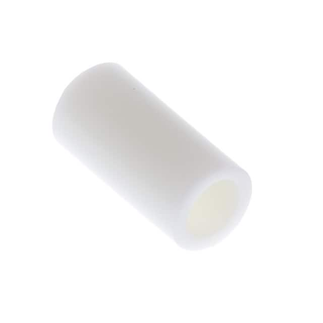
Design Guide for ROUND SPACER NYLON 9.4MM (908-370)
When engineers think about circuit design, they usually focus on ICs, passives, and connectors. But mechanical hardware like standoffs can make or break a prototype. The Bivar Inc. 908-370 is a round nylon spacer, 9.4 mm long, with a typical inner diameter of 3.2 mm (for M3 screws) and an outer diameter of 6.4 mm. Its nylon 6/6 construction provides electrical insulation, corrosion resistance, and slight vibration damping. This tutorial uses the 908-370 to build a compact, stackable sensor interface board where board-to-board spacing is critical for airflow and connector alignment.
Design requirements and specifications: We need a two-board stack: a main controller PCB (80 mm x 60 mm) and a sensor breakout PCB (60 mm x 40 mm) mounted 9.4 mm above it. The stack must survive a 1 m drop onto concrete without the boards shorting or the standoffs cracking. Operating temperature: -20 °C to +70 °C. Four mounting holes per board, M3 clearance (3.2 mm). Power budget: 5 V at 250 mA. The sensor board has an I²C temperature/humidity sensor (SHT31) and a 3-axis accelerometer (LIS3DH). The main board carries an ESP32-S3 module, 3.3 V LDO, and JST-XH power connector. The 9.4 mm gap allows a 40 mm fan to push air between boards for thermal management.
Step-by-step design process: First, calculate mechanical stack height. The 908-370 spacer gives exactly 9.4 mm between board surfaces. Add PCB thickness: 1.6 mm each. Total stack height from bottom of lower board to top of upper board = 1.6 + 9.4 + 1.6 = 12.6 mm. Next, verify screw engagement. Use M3 x 16 mm pan-head screws. Thread length into spacer = 16 mm – 1.6 mm (top board) – 1.6 mm (bottom board) = 12.8 mm total, but each screw only passes through one board and threads into the spacer’s through-hole (nylon spacers are not threaded; they rely on screw threads cutting into nylon or use a nut). Correction: The 908-370 is a clearance spacer, not threaded. So use M3 screws with nuts on the bottom. Screw length = 9.4 mm + 1.6 mm + 1.6 mm + 2 mm for nut = 14.6 mm, so choose 16 mm screws. Torque: 0.4 N·m max to avoid crushing nylon. For electrical design, route all high-speed signals (I²C at 400 kHz) on the bottom layer of the top board to minimize loop area. Add a 100 nF decoupling cap per sensor. Calculate pull-up resistors for I²C: with 3.3 V bus, 2.2 kΩ gives rise time ~300 ns for 100 pF bus capacitance, well under 1 µs for fast mode.
Component selection rationale: The Bivar 908-370 was chosen over metal standoffs because nylon prevents galvanic corrosion with the aluminum enclosure and eliminates the need for insulating washers. Its 9.4 mm length matches the height of the JST-XH connector (9.0 mm) plus 0.4 mm clearance, allowing the power cable to pass between boards without bending. The 6.4 mm outer diameter provides a wide bearing surface, reducing PCB cracking under vibration. For the BOM: ESP32-S3-WROOM-1 (main MCU), AP2112K-3.3 LDO (low dropout, 600 mA), SHT31-DIS (I²C sensor), LIS3DH (accelerometer), 4x Bivar 908-370, 8x M3 x 16 mm stainless screws, 8x M3 nylon-insert lock nuts, 2x 2.2 kΩ 1% resistors, 4x 100 nF 50 V X7R capacitors.
Simulation tips: You cannot simulate nylon spacers in SPICE, but you can model their mechanical effect in FreeCAD or Fusion 360. Apply a 50 N compressive load to the stack and check for board deflection under 0.1 mm. For electrical simulation, use LTspice to verify the LDO stability with the 100 nF caps and a 250 mA load step. Look for ringing below 50 mV. Also simulate I²C rise time with the 2.2 kΩ pull-ups and 100 pF bus capacitance. The key mechanical simulation: modal analysis to find the first resonant frequency. With four 908-370 spacers at corners, the first mode should be above 200 Hz, avoiding typical motor vibration (30–120 Hz).
Prototype build and testing methodology: Solder all SMD components first using stencil and reflow. Then attach the four 908-370 spacers to the bottom board with M3 screws and nuts, finger-tight plus 1/8 turn. Place the top board over the spacers, insert screws from top, and secure with nuts underneath. Do not overtighten—nylon will strip. Test continuity between boards: resistance should be > 100 MΩ at 500 V DC (insulation test). Power up with a current-limited supply at 5 V, 300 mA limit. Measure current draw: expect 85 mA idle, 220 mA with Wi-Fi transmitting. Check I²C communication with an oscilloscope on SDA/SCL. Then perform a drop test: drop the assembly from 1 m onto a concrete floor, three times on each face. After each drop, verify I²C still works and no screws loosened.
Performance verification and optimization: After 10 drop tests, inspect the 908-370 spacers for cracks or whitening (stress marks). If any appear, switch to a larger outer diameter spacer or add a fifth center spacer. Measure thermal performance: run the ESP32 at full load for 30 minutes. The 9.4 mm gap with a 40 mm fan should keep the sensor board below 45 °C. If hotter, increase gap to 12.7 mm using two stacked 908-370 spacers (18.8 mm total) but recheck screw length. For vibration, use a shaker table at 10–500 Hz, 2 g RMS. The nylon spacers should damp resonance peaks by 3–5 dB compared to aluminum. Finally, verify that the 9.4 mm height allows the JST-XH connector to mate without strain. If not, add a 0.5 mm nylon washer under each spacer. The Bivar 908-370 proved reliable, but always prototype with the exact screw torque and environmental conditions of your application.