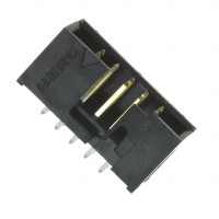
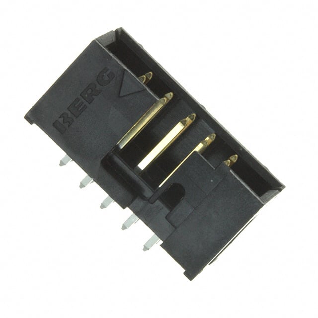
Application Note: CONN HEADER VERT 10POS 2.54MM (10056844-110LF)
The Amphenol ICC (FCI) 10056844-110LF is a 10-position vertical header with a 2.54 mm (0.100 inch) pitch, designed for through-hole board-to-board or wire-to-board interconnects. It is a general-purpose connector that appears in digital control, sensor interface, and power-signal distribution designs. Treating it as a mere mechanical part is a common mistake; the electrical and layout decisions around this header strongly influence signal integrity and long-term reliability. This note provides practical guidance for integrating the 10056844-110LF into new designs.
For circuit topology, the header is most often used to break out a mixed signal bundle between two PCBs or between a board and an off-board cable. A recommended practice is to dedicate at least one pin as a return path per every two to three signal pins when the bundle carries fast edges or moderate current. For purely low-speed digital or analog signals below a few megahertz, a single return pin in the header is usually sufficient, but do not rely on the chassis or mounting hardware as the sole return path. When the header carries differential pairs, assign adjacent pins to the pair and an adjacent return pin where possible. Because the pitch is 2.54 mm, the characteristic impedance of a pin pair in free air is on the order of 100 to 150 ohms, which is acceptable for many differential interfaces when the run length is short. For single-ended signals with rise times below 5 ns, treat the header as a lumped discontinuity and keep trace lengths on both sides matched to avoid skew.
Supporting passives are selected based on the signal class passing through the header. For power pins, place a bulk electrolytic or polymer capacitor of 10 uF to 100 uF within 10 mm of the header pin, plus a 100 nF ceramic for high-frequency decoupling. For signal pins that leave the board, series termination resistors of 22 to 33 ohms are effective at damping reflections when driving cables. If the header is used for I2C or other open-drain buses, pull-up resistors in the 2.2 kohm to 10 kohm range should be placed near the master, not at the header, to limit stub length. For analog sensor lines, a 100 ohm series resistor and a 1 nF capacitor to ground at the header form a useful low-pass filter against injected noise. Choose passives with X7R or C0G dielectrics for any filtering near the connector, since temperature drift in Y5V parts can degrade measurement accuracy.
PCB layout for the 10056844-110LF must account for the 2.54 mm through-hole pattern. Keep the connector footprint clear of tall components on both sides so that mating and de-mating does not stress nearby parts. Route signal traces away from the header at 90 degrees where possible, and avoid running sensitive traces directly beneath the pin field on the opposite layer, because the plated through-holes create a ground-plane perforation that can disturb return currents. Provide a solid ground plane on at least one inner layer, and stitch the ground plane with vias around the connector perimeter. For power pins, use a wide trace or a copper pour on the top layer to reduce IR drop; a 2.54 mm pin can carry roughly 3 A with a 10 degrees C temperature rise, but derate to 2 A for continuous use. If the header is near a board edge, leave at least 2 mm of clearance for the mating housing.
EMC and EMI performance depends largely on how the cable or mating board is terminated. The 10056844-110LF itself is not a shielded connector, so any cable leaving the assembly acts as an antenna. Always place a common-mode choke or a ferrite bead on off-board signal lines when the product must pass radiated emissions testing. A 100 ohm ferrite bead at 100 MHz in series with each signal, combined with a 22 pF capacitor to chassis ground, forms an effective pi filter. For the return path, bond the header ground pins to the chassis with a low-inductance connection, such as a 1 nF to 10 nF capacitor in parallel with a 1 Mohm resistor, to bleed static charge while blocking low-frequency ground loops. Keep the loop area between signal and return small by routing them adjacent on the PCB and twisting them in the cable harness.
Common pitfalls include using the header for signals that exceed its voltage rating (typically 250 VAC per pin, but check the datasheet for your specific variant), failing to account for mating cycle life (the 10056844-110LF is rated for a limited number of insertions, so do not use it as a frequent-connect interface), and ignoring the insertion force, which can be significant with 10 pins. Another frequent error is soldering the header with excessive heat, which can wick solder into the contact area and cause intermittent opens. Use a temperature-controlled iron at 350 degrees C maximum and limit contact time to 3 seconds per pin. Also, do not assume the pin numbering is sequential in a way that matches your schematic symbol; verify the actual pinout with a continuity test before powering the board.
For prototyping, solder the header to a breakout board and use a mating socket or a ribbon cable with crimped connectors to avoid repeated soldering. Bench testing should begin with a continuity check on every pin to the intended net, followed by an insulation resistance check between adjacent pins using a megohmmeter at 100 VDC. Apply a 1 kHz square wave through one pin and observe crosstalk on adjacent pins with an oscilloscope; keep crosstalk below 5 percent of the signal amplitude for digital lines. For power pins, load the header to its rated current for 30 minutes and measure the temperature rise with a thermocouple. Finally, perform a 10-cycle mating test and re-check contact resistance, which should remain below 20 milliohms per pin.