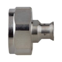
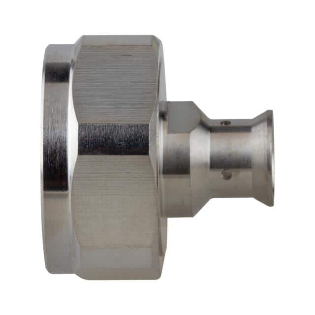
4.1/9.5 Male Low PIM RFD-4195-HPL Datasheet Guide: Specs & Uses
The RF Industries RFD-4195-HPL is a 4.1/9.5 male coaxial connector engineered specifically for low passive intermodulation (PIM) performance in cellular infrastructure applications. When interpreting its datasheet, the first specification an engineer must internalize is the interface standard itself: the 4.1/9.5 series, often referred to as the Mini-DIN connector, features a 4.1 mm inner contact diameter and a 9.5 mm outer contact diameter. This geometry is optimized for frequencies up to 3.8 GHz or higher, with a nominal characteristic impedance of 50 ohms. The datasheet will typically list a voltage standing wave ratio (VSWR) of less than 1.15:1 up to 3 GHz, which translates directly to return loss better than 23 dB. In practice, this means that in a distributed antenna system or a remote radio head, signal reflections are minimized, preserving both uplink sensitivity and downlink power efficiency. The low PIM specification is the defining feature: a typical PIM level of -160 dBc or better at 2 x 43 dBm (two carriers at 43 dBm each) is not merely a marketing number. It indicates that the connector's contact surfaces, plating, and mechanical junctions are designed to prevent nonlinear mixing of high-power RF carriers. Any oxide layer, loose metal-to-metal contact, or ferromagnetic material in the current path can generate intermodulation products that fall into a receive band, effectively desensitizing a base station. Therefore, the datasheet's PIM value should be read as a system-level guarantee only when the connector is mated with a corresponding low-PIM female and torqued to the specified value.
The absolute maximum ratings section of the datasheet is where purchasing decisions can go wrong if taken out of context. For the RFD-4195-HPL, you will find a maximum operating voltage of 500 V RMS and a dielectric withstanding voltage of 1500 V RMS. These are not continuous operating parameters; they are test limits. The continuous power handling, typically on the order of 500 W to 1 kW at 1 GHz depending on ambient temperature and cable assembly, is derated significantly as frequency increases due to skin effect and dielectric losses. The datasheet's derating curve, usually a plot of power versus frequency, is essential reading. At 2.5 GHz, for example, the allowable power might drop to 60 percent of the 1 GHz rating. Temperature derating is equally critical: the connector's PTFE dielectric and silver-plated or tri-metal-plated contacts have a maximum operating temperature of 165 degrees Celsius. Above 85 degrees Celsius ambient, the power handling must be further reduced to avoid dielectric softening and contact spring relaxation. An engineer specifying this connector for an outdoor small cell must account for solar loading, which can add 20 to 30 degrees Celsius to the ambient temperature inside an enclosure.
Typical application circuits for the RFD-4195-HPL are not discrete component networks but rather transmission line interfaces. The most common use is at the output of a remote radio unit (RRU) or the input of an antenna. The datasheet's application notes will often show a mated pair with a torque specification of 0.9 to 1.1 N·m (8 to 10 in-lb). This torque is not optional; under-torquing creates a high-resistance junction that generates PIM and can cause arcing at high power. Over-torquing deforms the outer contact fingers, permanently degrading return loss. The connector is designed for a cable assembly, typically with a 1/2-inch or 7/8-inch corrugated copper cable. The datasheet's assembly instructions will specify strip lengths and the use of a compression tool. In a typical MIMO antenna circuit, four or eight of these connectors feed a beamforming network. The low PIM characteristic ensures that the beamforming phase and amplitude relationships are not corrupted by passive mixing products.
Pin configuration for a coaxial connector is deceptively simple: one center pin and one outer body. However, the datasheet's mechanical drawing reveals critical dimensions. The center pin diameter for the male 4.1/9.5 is nominally 4.1 mm, and the outer body inner diameter is 9.5 mm. The interface dimensions must comply with IEC 61169-54. The male connector features a slotted outer contact that provides the spring force for the ground connection. The center pin is usually a solid brass pin with a silver or tri-metal plating. The datasheet will specify a mating life of 500 cycles, after which PIM performance may degrade. The package is a straight or right-angle bulkhead or cable mount. For panel mount, the datasheet provides the mounting hole diameter and panel thickness range. A common error is to assume that the connector's electrical performance is independent of the mounting torque on the bulkhead; excessive panel torque can distort the dielectric and change the impedance.
Thermal management for this connector is primarily about maintaining the dielectric's mechanical integrity and the contact plating's low resistance. The datasheet's thermal shock rating of -55 to +165 degrees Celsius covers storage and transport, but continuous operation should be limited to a derated range. The primary heat path is conduction through the center pin and outer body to the cable and panel. In high-power applications, forced air convection over the cable assembly can increase the allowable power by 15 to 20 percent. The datasheet may include a graph of temperature rise versus input power; a typical value is 30 degrees Celsius rise at 500 W. This means the connector's internal temperature is ambient plus 30 degrees. If the ambient is 70 degrees Celsius, the internal temperature is 100 degrees Celsius, well below the 165 degrees Celsius limit but high enough to accelerate oxidation of non-noble platings. This is why the RFD-4195-HPL uses a tri-metal plating (copper-tin-zinc) on the outer contact and silver on the center pin, which resist oxidation and maintain low PIM over time.
Finally, interpreting the characteristic curves is where a datasheet becomes a design tool. The VSWR versus frequency curve is usually a single trace with a maximum at the band edges. A flat curve below 1.15:1 from DC to 3 GHz indicates a well-matched interface. The PIM versus torque curve is less common but invaluable: it shows that PIM drops sharply as torque increases from 0.5 N·m to 0.9 N·m, then remains flat. The insertion loss curve is typically a straight line on a log-frequency plot, with a slope of about 0.1 dB per GHz for a mated pair. There are no timing diagrams for a passive connector, but the datasheet may include an intermodulation product versus carrier power plot. This plot often shows a slope of 3:1, meaning that for every 1 dB increase in carrier power, the PIM product increases by 3 dB. This is a critical purchasing consideration: if your system operates at 46 dBm per carrier instead of 43 dBm, the PIM will rise by 9 dB, potentially violating network operator requirements. Always verify that the datasheet's PIM specification is stated at your actual operating power and frequency band.