Design a 24V 550W AC/DC Converter: VMS-550C-24 Tutorial
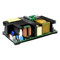
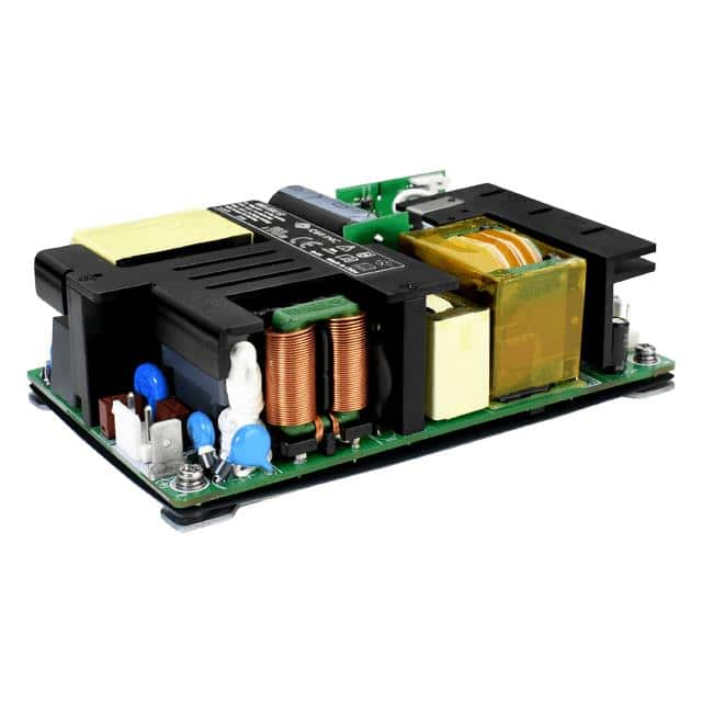
If you need to move serious power from a wall outlet to a 24V DC rail, the CUI Inc. VMS-550C-24 is a compelling starting point. This 550W enclosed AC/DC converter accepts a wide 90–264VAC input and delivers a regulated 24V output at up to 22.9A. It includes active PFC, over-voltage, over-current, and short-circuit protection, and it fits in a compact 5" x 3" footprint. For this tutorial, we will design a practical industrial control panel power stage that uses the VMS-550C-24 as the front-end, then distributes and conditions that 24V rail for a mix of DC motors, sensors, and logic.
Design requirements and specifications. Our target circuit must supply 24V at 20A continuous (480W) to a load bank that includes two brushed DC gearmotors (10A peak each, 5A continuous), a 5V/3A logic rail, and 12V/2A sensor rail. Input is universal AC 90–264VAC, 47–63Hz. We need bulk decoupling, inrush limiting, reverse polarity protection for the downstream branches, and a hold-up time of at least 20ms at full load to ride through brief AC dips. Efficiency target is greater than 88% at half load, and the entire assembly must fit within a 200mm x 150mm enclosure.
Step-by-step design process. First, calculate the input power. At 480W output and 90% efficiency, input power is 480 / 0.90 = 533W. The VMS-550C-24 is rated 550W, so we have a 3% margin—acceptable but tight. For derating, keep continuous load below 500W or ensure 30 CFM forced air. Second, size the bulk hold-up capacitor. The converter already has internal holdup, but for 20ms at 480W, energy needed is 480W x 0.02s = 9.6J. On a 24V rail, C = 2E / (V1² – V2²). Allow the rail to drop from 24V to 20V: C = 2 x 9.6 / (576 – 400) = 19.2 / 176 = 0.109F, or 109,000µF. That is large, so instead we rely on the converter’s internal hold-up and add a modest 10,000µF electrolytic for transient suppression only. Third, design the 5V and 12V rails using buck converters. For 5V at 3A from 24V, duty cycle is 5/24 = 21%. Choose a synchronous buck controller like the LM5116. Inductor: L = (Vout x (1 – D)) / (fsw x ΔI). With fsw = 250kHz and ΔI = 30% of 3A = 0.9A, L = (5 x 0.79) / (250k x 0.9) = 17.5µH. Use a 22µH standard value. Output cap: Cout = ΔI / (8 x fsw x ΔV). For ΔV = 50mV, Cout = 0.9 / (8 x 250k x 0.05) = 9µF. Use two 22µF ceramics.
Component selection rationale. The VMS-550C-24 itself needs a 10A slow-blow fuse on the AC line and a 275VAC MOV for surge. Downstream, use a 40V, 30A Schottky diode (e.g., MBR3040) for reverse polarity protection on the 24V bus. For the 5V and 12V bucks, select 60V N-channel MOSFETs (e.g., Infineon BSC0902NSI) with low Rds(on) to keep conduction losses low. The 24V bus decoupling uses a 10,000µF, 35V low-ESR electrolytic (Panasonic FR series) in parallel with a 10µF ceramic. For the 5V output, use a 22µH shielded inductor rated 5A saturation. Sense resistors for current limiting: 5mΩ, 1% for the 24V bus. All connectors must be rated 20A minimum—use Molex Mega-Fit or equivalent.
Simulation tips. Before building, simulate the 5V buck in LTspice or PLECS. Look for inductor current ripple staying below 30% of load, output voltage overshoot under 100mV during a 1A to 3A load step, and switch node ringing below 30V. For the 24V bus, simulate the converter as a behavioral model with a 20ms AC dropout to verify the rail stays above 20V. Pay attention to the input filter: the VMS-550C-24 has internal EMI filtering, but add a 100µH common-mode choke and 0.1µF Y-caps if your application is noise-sensitive.
Prototype build and testing methodology. Assemble the AC input section first—fuse, MOV, and terminal block—then verify with a variac at 120VAC and no load. Measure the 24V output with a scope (use a differential probe or isolation transformer). Next, add the 5V and 12V bucks on a separate board and test them from a bench supply before connecting to the 24V bus. Once integrated, load the 24V bus with a programmable electronic load at 5A, 10A, and 15A. Check efficiency with a power analyzer. For thermal testing, run at 400W for 30 minutes and measure the VMS-550C-24 case temperature—it should stay below 90°C with 30 CFM airflow.
Performance verification and optimization. Verify load regulation: 24V should stay within ±2% from no load to 20A. Check transient response: a 10A load step should not cause more than 500mV deviation. For optimization, add a small RC snubber across the 24V output rectifier if ringing exceeds 30V. If efficiency is below target, reduce the switching frequency of the bucks to 150kHz or use a synchronous rectifier on the 5V rail. Finally, confirm hold-up time by dropping AC input for 20ms and monitoring the 24V rail—if it dips below 20V, add more bulk capacitance or reduce load during the dip.