Application Note: CONN PLUG HSG 8POS 2.20MM (1379659-1) Design Guide
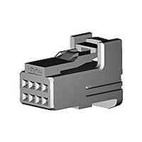
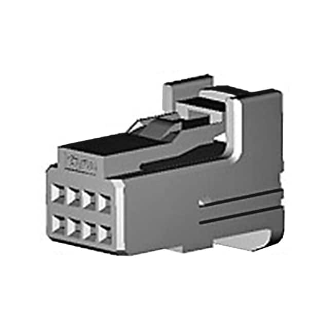
The TE Connectivity AMP Connectors 1379659-1 is an 8-position plug housing designed for a 2.20 mm pitch wire-to-board or wire-to-wire interconnect system. It is a crimp-style housing that accepts discrete wire contacts, making it well suited for signal and low-power distribution in automotive, industrial, and consumer electronics. Because the housing itself is a mechanical interface, the electrical performance of your design will be determined primarily by the mating header, the crimped terminals, the wire gauge you select, and the PCB layout of the header footprint. Design engineers should treat this connector as one element of a complete interconnect system and plan the surrounding circuitry accordingly.
For circuit topology, this connector is most commonly used for point-to-point signal routing and low-current power distribution. Typical applications include sensor harnesses, control panel interfaces, and board-to-board interconnects where a removable cable assembly is required. When routing multiple signals through the connector, avoid mixing high-current power and sensitive analog or high-speed digital lines in adjacent positions unless you provide adequate separation. A practical approach is to assign the outer positions to power and ground returns and reserve the center positions for differential or sensitive signals. If the connector is used for power delivery, derate the current per contact based on the wire gauge and terminal used; the housing alone does not define a current rating. For multi-position connectors carrying a common ground, use multiple contacts for ground return to reduce impedance and improve signal integrity.
Supporting passives should be selected based on the signal environment and the cable length. For low-frequency digital or analog signals, series termination resistors in the 22 to 100 ohm range at the source end can reduce ringing and overshoot. For power pins, place a bulk decoupling capacitor of 10 uF to 100 uF near the header, supplemented by 0.1 uF ceramic capacitors for high-frequency noise. If the cable assembly is long or routed near noisy sources, add common-mode chokes or ferrite beads on the signal lines, choosing a bead with a impedance peak in the frequency range of concern. TVS diodes or ESD protection devices should be placed on any line that exits the enclosure, with the clamp voltage selected below the absolute maximum ratings of the receiving IC. Always verify that the voltage rating of the passives exceeds the maximum transient voltage expected on the harness.
PCB layout for the mating header is critical. Place the header close to the board edge to allow the cable assembly to mate without strain, and provide strain relief either through the housing latches or an external tie-down. Keep the trace lengths from the header to the receiving components as short as practical, and route power and ground traces with adequate width for the expected current. For a 2.20 mm pitch connector, use a footprint that matches the manufacturer's recommended land pattern; do not shrink pads or reduce annular rings, as this can lead to solder joint failure. Avoid routing high-speed traces directly beneath the connector body, because the plastic housing can affect impedance and coupling. If the connector is on a multilayer board, provide a solid ground plane beneath the header to control return paths and reduce radiated emissions.
EMC and EMI considerations begin with cable management. The cable attached to this plug housing acts as an antenna, so keep cable lengths as short as possible and route them away from noise sources such as switching regulators, motor drivers, and clock lines. If the cable must be long, use shielded cable with the shield terminated to the chassis or ground plane at both ends, or use a ferrite sleeve around the cable near the connector. On the PCB, filter every line that leaves the board with a pi-filter or RC filter if the signal bandwidth permits. For differential signals, maintain tight coupling and matched lengths from the header to the receiver. Ground the connector housing to the chassis if it is a metal shell version; for plastic housings, ensure that the ground return path is low impedance and that any cable shield is properly terminated.
Common design pitfalls include using the wrong wire gauge or insulation diameter, which can prevent proper crimping or cause the contact to back out of the housing. Always use the specified terminal for the housing and verify the wire insulation diameter falls within the terminal's range. Another pitfall is inadequate strain relief, leading to cracked solder joints or broken wires. Do not rely on the connector's friction lock alone for high-vibration environments; add a secondary latch or cable tie. Avoid over-tightening the mating header during assembly, as this can damage the housing or contacts. Finally, do not assume that the housing provides environmental sealing; if moisture or dust is a concern, select a sealed version or add conformal coating to the PCB assembly.
For prototyping, start with a small batch of crimped wire assemblies and verify pull-force on each contact using a tension gauge. Perform a continuity test on all eight positions before mating. On the bench, apply the maximum expected voltage and current to the power pins and measure temperature rise on the connector and wire after 30 minutes. Use an oscilloscope with a near-field probe to check for unexpected emissions around the cable. If the design includes high-speed signals, perform eye-diagram measurements at the receiver with the cable connected. For EMC pre-compliance, run a quick scan in a temporary setup to identify resonant frequencies. Document the mating cycle count and inspect contacts for wear after repeated insertions. These steps will help you catch issues early and ensure a reliable interconnect in the final product.