ACMI MV-9086L (WW-02L7-7) Replacement Guide: Component Design Tutorial
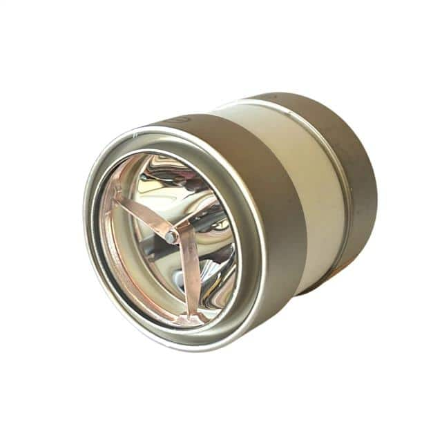
The Interlight WW-02L7-7 is a direct replacement lamp for the ACMI MV-9086L, a high-intensity xenon short-arc lamp used in medical endoscopy towers. While designed as a drop-in replacement, this lamp is an excellent teaching component for a hands-on power electronics tutorial because it combines a high-voltage ignition requirement, a low-voltage high-current steady-state operating point, and strict thermal constraints. Students learn to design a ballast that can strike and then regulate a lamp whose impedance changes dramatically between modes. The WW-02L7-7 typically operates at 14–16 VDC and 5–7 A after ignition, but requires a 20–30 kV pulse to ionize the xenon gas. This tutorial builds a practical 75 W lamp driver around that specification.
Design requirements and specifications. The circuit must deliver a 25 kV, 100 ns ignition pulse, then transition to a regulated 15 VDC at 6 A (90 W) within 50 ms. Input is 24 VDC from a medical-grade supply. Efficiency must exceed 85% to limit heat in the endoscope tower. Safety requires galvanic isolation between the low-voltage control and the high-voltage output, plus a 10 ms maximum arc-fault shutdown. The lamp’s negative temperature coefficient demands current-mode control to prevent thermal runaway. Target size is 80 mm × 50 mm, using surface-mount components where possible.
Step-by-step design process. First, calculate the steady-state load: R_lamp = 15 V / 6 A = 2.5 Ω. For a buck-derived current regulator from 24 V, duty cycle D = V_out / V_in = 15 / 24 = 0.625. Choose a switching frequency of 200 kHz to keep the inductor small. Inductor ripple current ΔI_L = 30% of 6 A = 1.8 A. L = (V_in − V_out) × D / (f_sw × ΔI_L) = (24 − 15) × 0.625 / (200,000 × 1.8) = 15.6 µH. Use a 15 µH, 10 A saturation-rated inductor. Output capacitor for 50 mV ripple: C_out = ΔI_L / (8 × f_sw × ΔV_out) = 1.8 / (8 × 200,000 × 0.05) = 22.5 µF; choose 47 µF to derate for ESR and aging. Current-sense resistor: R_sense = 100 mV / 6 A = 16.7 mΩ; use a 15 mΩ, 1 W shunt. For ignition, a flyback converter charges a 1 nF capacitor to 25 kV through a step-up transformer with a 1:100 turns ratio. Primary voltage is 250 V, so the flyback switch must withstand 400 V. Peak primary current I_pk = 2 × E / (L_p × t_on) — with E = ½ C V² = 0.5 × 1 nF × (25 kV)² = 0.3125 J, L_p = 100 µH, and t_on = 10 µs, I_pk = 7.9 A. Select a 600 V, 12 A MOSFET.
Component selection rationale. The main buck controller is an LT3763 because it includes current-mode regulation, PWM dimming, and a 100 V input range. The flyback ignition switch is an STP16NF06L for its low gate charge and avalanche rating. The step-up transformer uses a ferrite E-core with a 1:100 turns ratio and 4 kV isolation between windings. The high-voltage capacitor is a 1 nF, 30 kV ceramic disc (Murata DHR series). The current shunt is a Vishay WSBS8518 with 1% tolerance and low inductance. The output inductor is a Coilcraft XAL1510-153 with shielded construction to reduce EMI. For isolation, use a Si8261 opto-driver for the high-side gate. All high-voltage traces must have 8 mm creepage and a conformal coating.
Simulation tips. Model the lamp as a behavioral resistor that switches from 1 MΩ to 2.5 Ω when the ignition pulse exceeds 20 kV. Use LTspice with a .param statement for the transition. Look for three things: (1) ignition pulse width must be under 200 ns to avoid electrode erosion; (2) the buck inductor current must not exceed 8 A during the strike-to-run transition; (3) the output voltage overshoot must stay below 20 V. Add a 10 µs dead time between ignition and buck enable to let the arc stabilize. Monitor junction temperature of the MOSFET using a thermal RC network.
Prototype build and testing. Build the low-voltage buck first on a 2-layer FR-4 board with 2 oz copper. Test with a 2.5 Ω, 100 W resistive load. Verify current regulation from 10% to 100% load. Then add the flyback ignition circuit on a separate daughterboard with a ground plane cutout under the transformer. Use a 1000:1 high-voltage probe (Tektronix P6015A) to measure the ignition pulse. Never touch the lamp terminals during operation. Test the arc-fault shutdown by shorting the output; the controller must disable PWM within 10 ms. Run the lamp for 10 minutes and measure case temperature; it must stay below 90°C.
Performance verification and optimization. Measure efficiency at 24 V input and 15 V, 6 A output. If below 85%, reduce switching frequency to 150 kHz or use a synchronous buck. Check conducted EMI from 150 kHz to 30 MHz; add a common-mode choke if needed. For optical stability, add a 100 µF low-ESR capacitor across the lamp to reduce 120 Hz flicker. Optimize the ignition pulse by adjusting the flyback primary inductance — higher L_p reduces peak current but lengthens charge time. Finally, verify that the WW-02L7-7 replacement lamp maintains the same 15 V, 6 A operating point as the original ACMI MV-9086L; small differences in electrode gap may require trimming the current setpoint by ±5%.