Design Guide for M3 Steel Round Standoffs in Compact PCB Builds
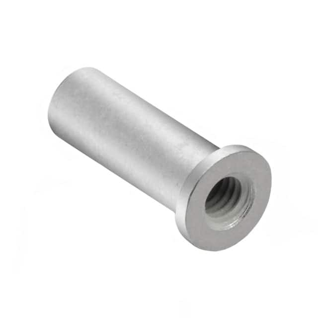
Mechanical spacers are often overlooked in circuit design until a prototype fails because a PCB flexes, a connector misaligns, or a heatsink shorts to a trace. This tutorial uses the Würth Elektronik ROUND STANDOFF M3 STEEL 1MM, SKU 9775096360R as the central mechanical component in a practical, repeatable design. The part is a 1 mm tall, M3-threaded round standoff made of steel, with a hexagonal or knurled body depending on the exact series. Its 1 mm height is the key feature: it provides precise, minimal board-to-board or board-to-chassis spacing in tight enclosures where standard 5 mm or 10 mm standoffs are too tall.
What makes this standoff suitable for a tutorial is that it forces you to think about mechanical tolerances, thread engagement, and electrical isolation at the same time as circuit performance. It is inexpensive, widely available, and easy to model in CAD. The 1 mm height also makes it ideal for low-profile sensor nodes, wearable prototypes, and stacked PCBs where vertical space is at a premium.
Design requirements and specifications. We will design a low-profile environmental sensor node. The circuit includes a 3.3 V LDO regulator, an I2C temperature and humidity sensor, and a 2.4 GHz radio module. The PCB is 40 mm by 25 mm, 1.6 mm thick FR-4. The enclosure is a 3D-printed shell with a 6 mm internal height. The design must survive a 1 m drop onto concrete, operate from -20 °C to 60 °C, and maintain a minimum clearance of 0.5 mm between the bottom of the PCB and any conductive enclosure features. The standoff will mount the PCB to the enclosure base and provide the required 1 mm air gap.
Step-by-step design process. First, calculate the mechanical stack. The enclosure base is 2 mm thick. The standoff is 1 mm tall. The PCB is 1.6 mm thick. The top of the radio module is 2.2 mm above the PCB. Total internal height used is 2 + 1 + 1.6 + 2.2 = 6.8 mm. That exceeds the 6 mm enclosure, so we must either reduce the standoff height or recess the standoff into the enclosure base. We choose to recess the standoff by 1 mm into a counterbore, which brings the total to 5.8 mm and leaves 0.2 mm clearance. This is tight but acceptable for a non-flexing, rigid assembly.
Second, calculate thread engagement. An M3 screw into a steel standoff needs at least 3 mm of engagement for full strength. The standoff is 1 mm tall, so it cannot accept a screw from both sides. We will use a pan-head M3 screw from the bottom of the enclosure into the standoff, and the PCB will be captured between the standoff top and a second M3 screw from the top. The bottom screw engages the enclosure's heat-set insert, not the standoff. The standoff itself acts as a spacer and a threaded nut for the top screw. The top screw must be no longer than 1 mm plus the PCB thickness plus 3 mm engagement, or 5.6 mm. A 5 mm screw is ideal.
Third, verify electrical isolation. Steel is conductive. The standoff touches the PCB around a mounting hole. We must keep a 1.5 mm annular ring of bare FR-4 around the hole, with no copper pour or traces. We also add a nylon washer under the top screw head to prevent galvanic corrosion and to provide a small amount of compliance. The standoff's 1 mm height ensures that even if the PCB flexes 0.5 mm, the standoff does not contact any components on the bottom side.
Component selection rationale. The Würth 9775096360R is chosen because its 1 mm height matches the counterbore depth exactly, its steel body handles the torque of M3 screws without stripping, and its round shape distributes compressive load evenly. The mating screws are A2 stainless steel M3 x 5 mm pan head. The heat-set inserts are brass M3, 4 mm long, installed in the 3D-printed enclosure. The nylon washers are M3 x 0.5 mm. The PCB uses 3.2 mm mounting holes to clear the M3 threads. The LDO is an AP2112K-3.3, the sensor is an SHT31-DIS, and the radio is an nRF24L01+ module. All are low-profile and fit within the 6 mm envelope.
Simulation tips. Use a simple finite element analysis (FEA) in FreeCAD or Fusion 360 to model the PCB as a 1.6 mm FR-4 plate with the four standoffs as fixed supports. Apply a 50 N downward force at the center of the PCB to simulate a drop or a heavy component. Look for maximum deflection under 0.2 mm and maximum stress under 30 MPa. Also run a thermal simulation with the radio transmitting at 0 dBm. The steel standoff will conduct heat away from the PCB slightly, but its 1 mm height limits the effect. Check that the sensor does not see more than a 2 °C rise from the radio.
Prototype build and testing methodology. Print the enclosure with 0.2 mm layer height and 40 percent infill. Install the heat-set inserts with a soldering iron at 250 °C. Place the standoffs in the counterbores. Mount the PCB with the nylon washers and M3 screws. Tighten to 0.4 N·m using a torque screwdriver. Perform a continuity test between the standoff and any ground plane to confirm isolation. Then run a 1 m drop test onto concrete, six times, from different orientations. After each drop, check for cracked solder joints, loose screws, and sensor drift.
Performance verification and optimization. Measure the sensor accuracy before and after the drop test. The SHT31 should hold ±2 percent relative humidity and ±0.3 °C. If drift exceeds this, add a small bead of silicone between the standoff and the PCB to damp vibration. Measure the radio range in free space. The 1 mm standoff does not affect RF performance because the antenna is kept 5 mm away from the standoff. If the enclosure feels too tight, reduce the standoff height to 0.8 mm by sanding the top face, but re-check thread engagement. For production, switch to a 1 mm nylon standoff if electrical isolation is critical, but the steel version is stronger and cheaper for prototypes.