VBN2AGPX6102 Electric Ball Valve Datasheet Guide: Specs & Wiring
The Honeywell VBN2AGPX6102 is a two-way, spring-return control ball valve with an electric actuator, designed for modulating or floating control of hot and chilled water in HVAC systems. Unlike a semiconductor datasheet, this device combines a mechanical valve body with an electromechanical actuator, so interpreting its specification sheet requires attention to both fluid-handling and electrical parameters. The key electrical specifications begin with the supply voltage, typically 24 VAC ±10% at 50/60 Hz for this series, though some variants accept 24 VDC. The actuator's power consumption is rated in VA, often around 7.5 VA during rotation and significantly lower in the holding position. The control signal, if the valve is modulating, is usually 0–10 VDC or 4–20 mA, with an input impedance of approximately 100 kΩ for voltage input. In practice, these figures tell you the transformer sizing and wiring gauge needed: a 24 VAC transformer must supply at least the sum of all actuator VA ratings on the same circuit, plus a 20% margin for inrush. The 0–10 VDC signal means the valve stem position is proportional to the command voltage, so a controller with limited output current can still drive multiple actuators in parallel if the total input impedance remains above the controller's minimum load. Always verify whether the actuator is floating (three-wire, two-position) or modulating (proportional), because the VBN2AGPX6102's suffix often indicates a specific control mode.
Absolute maximum ratings and derating considerations for this valve are less about junction temperature and more about fluid and ambient limits. The valve body is typically rated for a maximum static pressure of 300 psi (20.7 bar) and a close-off pressure differential that depends on actuator torque. For the VBN2AGPX6102, the close-off rating is often 50 psi for 1/2-inch to 3/4-inch sizes. Exceeding this differential will prevent the actuator from seating the ball, causing continuous flow and actuator stall. The fluid temperature range is usually 34°F to 250°F (1°C to 121°C) for standard EPDM seals, but derate to 200°F if the actuator is mounted in a confined space where ambient exceeds 122°F (50°C). Ambient temperature derating is critical: the actuator's internal motor and gearing are rated for 32°F to 122°F. Above 104°F, torque output drops by roughly 10% per 18°F rise, so a valve that closes against 50 psi at 70°F may only close against 40 psi at 110°F. Never exceed the maximum fluid temperature without checking the seal material—some Honeywell variants use Viton for higher temperatures, but the VBN2AGPX6102 typically uses EPDM. Also, the actuator is not rated for condensing or dripping water; if condensation is possible, install a drip shield or specify a NEMA 4X enclosure.
Typical application circuit analysis for this valve involves a 24 VAC transformer, a controller (e.g., a DDC or PLC), and the actuator's wiring harness. The actuator has three or four conductors: common, power, and control signal. For a floating control version, two power wires drive the motor open or closed, and a third common returns. For modulating, a fourth wire carries the 0–10 VDC command. A typical circuit places the transformer secondary across the actuator's power terminals, with the controller's analog output connected to the signal input and the signal common tied to the transformer common. Always use a separate transformer for the actuator if the controller's power supply is not isolated, to avoid ground loops that can cause erratic positioning. Add a 1 A slow-blow fuse in the 24 VAC line to protect the actuator's motor from short circuits. If the valve is used in a closed-loop control, the feedback signal (if provided) is usually a 0–10 VDC output proportional to stem position; this can be wired back to the controller for position verification. For fail-safe operation, the spring-return mechanism drives the valve to its normal position (typically closed for heating, open for cooling) within 15 to 30 seconds upon power loss, so the controller must account for this transition in its sequencing logic.
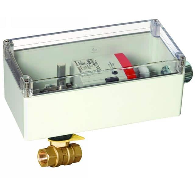
Pin configuration and package considerations are straightforward but often misread. The electrical connection is made via a pre-wired cable or a terminal block on the actuator housing. The wire colors follow Honeywell's standard: black (common), red (24 VAC hot), white (control signal for modulating), and orange or yellow (feedback). The valve body itself has NPT or sweat connection sizes, typically 1/2-inch to 1-inch for this SKU. The actuator can be rotated in 90-degree increments on the valve body for wiring clearance, but never force it beyond the stops. The package is a cast bronze or brass body with a stainless steel ball and stem. The actuator housing is polycarbonate, rated for indoor use only. When mounting, ensure the actuator is not inverted unless the manufacturer allows it—most Honeywell ball valve actuators can be mounted in any orientation except upside down, where condensation could pool in the motor. The cable entry is a 1/2-inch conduit fitting; use a strain relief to prevent pulling on the terminal block.
Thermal management guidelines for this device focus on ambient and fluid heat transfer. The actuator generates heat from the motor and gearing, but the primary thermal path is conduction through the valve stem from the fluid. If the fluid is above 200°F, the stem conducts heat into the actuator, potentially exceeding its ambient rating. In such cases, use a thermal isolation kit or mount the actuator below the pipe if the fluid is cold, and above if hot—this uses convection to keep the actuator cooler. Do not insulate the actuator; it relies on free air convection. Allow at least 2 inches of clearance around the actuator for air circulation. If the valve is in a ceiling plenum where ambient can reach 140°F, derate the close-off pressure by 30% or select a higher-torque actuator. The spring-return mechanism is mechanical and not affected by temperature, but the motor's winding insulation is Class B, limiting the maximum ambient to 122°F.
Reading the timing diagrams and characteristic curves is essential for predicting performance. The timing diagram for a modulating actuator shows command voltage on the X-axis and stem position on the Y-axis. The curve is typically linear within ±5%, but near the endpoints, there is a deadband of 0.5 V to prevent hunting. The full stroke time is usually 90 to 120 seconds for 90-degree rotation. For floating control, the diagram shows open and close pulses; the minimum pulse width is 0.5 seconds, and the actuator will not respond to pulses shorter than that. The characteristic curve for flow versus stem position is not linear for a ball valve—it is approximately equal-percentage, meaning a 50% stem position gives about 20% flow. This is critical for sizing: do not assume linearity when tuning a PID loop. The close-off pressure curve shows the maximum differential pressure the actuator can hold at a given supply voltage; at 24 VAC ±10%, the torque drops by 15% at 21.6 VAC, so the close-off rating must be derated accordingly. Always use the curves at the actual supply voltage, not the nominal, to avoid undersizing the valve for the application.