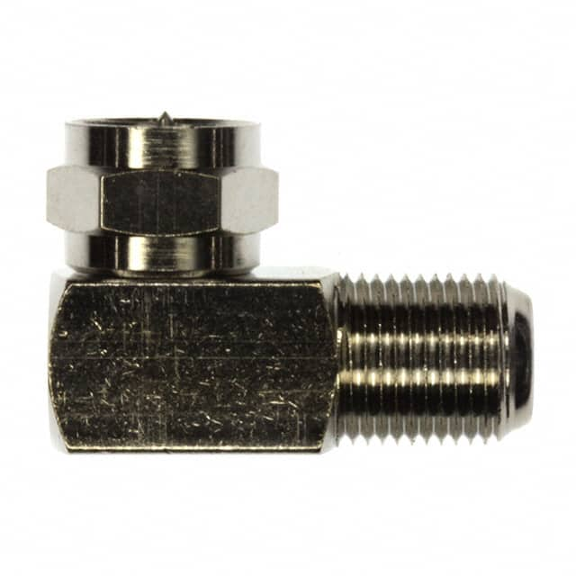
Design Guide: Using the 5-1634537-1 F Type Plug-to-Jack Adapter
If you have ever needed to inject a test signal into a television receiver, spectrum analyzer, or vintage radio without permanently modifying the equipment, an F-type adapter is the simplest solution. The TE Connectivity AMP Connectors part number 5-1634537-1 is a 75-ohm F-type plug-to-jack adapter that lets you insert a test point or a signal source between two existing F cables. It is a straight-through adapter, meaning the center conductor and shield pass directly from the male plug on one end to the female jack on the other. This makes it ideal for a hands-on tutorial because it requires no soldering to the adapter itself, yet it forces you to think about impedance, shielding, and signal integrity.
The tutorial project is a 75-ohm RF tap and bias tee for testing cable TV or antenna signals. You will build a small board that sits between the adapter and your test equipment, allowing you to measure signal levels and optionally inject DC power onto the coax. The design requirements are: frequency range 1 MHz to 1 GHz, insertion loss below 1.5 dB, return loss better than 15 dB, and DC blocking on the measurement port. The adapter’s 75-ohm characteristic impedance and 1 GHz rated bandwidth make it suitable for this range. Its brass body and PTFE insulator provide stable electrical performance and mechanical durability.
Step 1: Define the interface. The adapter’s plug end connects to the source cable. The jack end connects to your circuit board’s F female connector. You need a 75-ohm microstrip or coplanar waveguide on FR-4. For 1 GHz, FR-4 is acceptable if you keep traces short. Calculate the trace width for 75 ohms using a standard microstrip calculator. For 1.6 mm FR-4 with 1 oz copper, a trace width of about 1.2 mm gives 75 ohms. Keep the trace length under 20 mm to limit loss.
Step 2: Design the tap. Use a resistive divider. For a 20 dB tap, the series resistor R1 and shunt resistor R2 must maintain 75 ohms at the input. The tap port sees a 75-ohm load. The equations are: R1 = Z0 (10^(A/20) - 1) / (10^(A/20) + 1) and R2 = Z0 2 10^(A/20) / (10^(2A/20) - 1). For A = 20 dB, 10^(A/20) = 10. R1 = 75 9 / 11 = 61.36 ohms. R2 = 75 * 20 / 99 = 15.15 ohms. Use 61.9-ohm and 15-ohm 1% resistors. The tap output is about 20 dB below the input, so a -20 dBm signal becomes -40 dBm, which most spectrum analyzers can detect.
Step 3: Add the bias tee. To inject DC without affecting RF, use an inductor from the DC input to the center conductor. Choose a 1 µH inductor with a self-resonant frequency above 1 GHz. A Coilcraft 0603CS-1N0 or similar. Add a 100 nF DC blocking capacitor on the measurement port. The capacitor must have low ESR at 1 GHz; use a 0402 C0G type.
Step 4: Component selection rationale. The adapter is the mechanical interface. The F female connector on the board should be a 75-ohm PCB mount, such as Amphenol 901-143. The resistors should be thin-film 1% 0805 for low parasitics. The inductor should be wirewound ceramic for high Q. The blocking capacitor should be C0G for stability. All traces must be 75 ohms. Use a ground plane with via stitching every 5 mm.
Simulation tips. Use LTspice or Qucs to simulate the tap and bias tee. Include parasitic inductance of 1 nH per mm of trace and capacitance of 0.1 pF per pad. Look for return loss dips at 500 MHz and 1 GHz. If return loss is worse than 15 dB, adjust the resistor values slightly or shorten the trace. Also simulate the DC path to ensure the inductor does not resonate with the blocking capacitor.
Prototype build. Solder the F female connector to the board. Connect the adapter’s jack to the board’s female connector. Connect the adapter’s plug to a signal generator. Terminate the tap port with a 75-ohm load. Measure insertion loss from input to output using a network analyzer or a signal generator and power meter. Measure return loss with a directional coupler or a VNA. Test at 10 MHz, 100 MHz, 500 MHz, and 1 GHz.
Testing methodology. First verify DC continuity. Then apply a 1 MHz sine wave at 0 dBm. Measure output at the through port and tap port. The through port should be within 1.5 dB of input. The tap port should be 20 dB lower. Then sweep to 1 GHz. If loss increases sharply, check for trace discontinuities. If return loss is poor, check the ground plane and connector soldering. For the bias tee, apply 12 V DC through the inductor and verify no RF leakage to the DC supply.
Performance verification and optimization. Use a VNA to measure S11 and S21. Aim for S11 below -15 dB and S21 above -1.5 dB from 1 MHz to 1 GHz. If not, try a different resistor value or add a small series inductor to tune out capacitance. You can also replace the FR-4 with Rogers 4003 for lower loss. The adapter itself contributes less than 0.2 dB loss up to 1 GHz, so most loss comes from the board. Optimize by keeping the ground plane continuous and minimizing the distance between the adapter and the tap resistors.