76RSB03L Application Note: Design Guide for Reliable Circuits
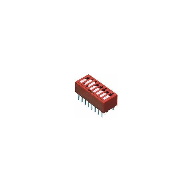
The Grayhill 76RSB03L is a three-position DIP switch from the 76 series, featuring a rocker actuator and a sealed construction that makes it suitable for applications requiring reliable, low-current signal selection. When integrating this component into your design, the most common topology is a simple pull-up or pull-down configuration in which one side of each switch is tied to a common rail and the other side feeds a digital input. For the 76RSB03L, which is a single-pole single-throw device, each switch position is electrically independent. A straightforward approach is to connect the common pin to ground and use individual pull-up resistors on each signal line, so that closing a switch pulls the input low. Alternatively, you can tie the common to VCC and use pull-down resistors. The choice depends on your logic polarity and power sequencing. Avoid leaving any switch input floating when the switch is open; always provide a defined logic level through a pull-up or pull-down resistor. For multi-position selection, you can also use the switches to set addresses or configuration bits on an I2C multiplexer or a microcontroller's boot strapping pins. In such cases, ensure the switch's contact rating (typically 100 mA at 30 VDC for this series) is not exceeded, though these are signal-level devices and should never be used to switch inductive loads directly.
Selecting supporting passives for the 76RSB03L is straightforward but deserves attention. The pull-up or pull-down resistor value should balance power consumption against noise immunity. A common choice is 10 kΩ, which draws 0.5 mA at 5 V and provides a reasonable trade-off. If your application runs at 3.3 V, a 4.7 kΩ resistor offers similar current draw and faster rise times. For very low-power designs, you can increase the resistor to 100 kΩ, but be aware that the switch's contact resistance (typically 50 mΩ maximum) becomes less significant, and leakage currents may cause false readings. In noisy environments, add a 100 nF ceramic capacitor from each signal line to ground to form an RC low-pass filter with the pull-up resistor. This capacitor also helps debounce the switch mechanically. For debouncing in software, a simple delay of 1–5 ms after detecting a change is usually sufficient. If you need hardware debouncing, a Schmitt-trigger buffer such as a 74HC14 can be placed after the RC network. Do not use electrolytic capacitors for this purpose; use X7R or C0G dielectrics for stability over temperature.
PCB layout for the 76RSB03L should follow standard good practices for through-hole or surface-mount DIP switches. Keep the switch close to the microcontroller or logic input to minimize trace length. Route the signal traces away from high-speed clocks, switching regulators, and other noise sources. If the switch is used for configuration that is read only at power-up, you can place it farther away, but still avoid running its traces parallel to noisy lines. Use a solid ground plane on the bottom layer or a ground fill on the top layer to provide a low-impedance return path. For the pull-up resistors, place them near the switch or near the input pin—either is acceptable, but placing them near the input pin reduces the loop area of the signal trace. If you use the optional RC filter, place the capacitor as close to the input pin as possible. The 76RSB03L has a standard 0.100-inch pin pitch, so ensure your footprint matches the manufacturer's recommended land pattern. For hand soldering, leave adequate clearance around the switch body to avoid overheating the plastic housing.
EMC and EMI considerations for the 76RSB03L are primarily about preventing noise from coupling into the switch lines and preventing the switch lines from radiating. Because the switch is a passive, low-frequency device, it is not a significant source of emissions. However, the traces connected to it can act as antennas if they are long and unshielded. Keep trace lengths under a few inches where possible. If the switch is mounted on a panel away from the PCB, use a shielded cable or twisted pair for the connection, with the shield grounded at one end. Add a series resistor (100 Ω to 1 kΩ) at the input pin to limit current during ESD events. For added protection, a TVS diode or a small capacitor (10–100 pF) from the signal line to ground can shunt high-frequency transients. In automotive or industrial environments, consider using a ferrite bead in series with the signal line. Always ensure the switch's common pin is connected to a clean ground or power rail, not a noisy one. If the switch is used in a human-interface context, the metal actuator or panel may need a separate ground connection to meet ESD requirements.
Common design pitfalls with the 76RSB03L include forgetting pull-up or pull-down resistors, which leads to floating inputs and erratic behavior. Another mistake is using the switch to directly drive an LED or relay without a transistor, which can exceed the contact rating and cause premature failure. Designers also sometimes overlook the switch's sealed construction and assume it is waterproof; while it is sealed against flux and cleaning solvents, it is not rated for immersion. Avoid placing the switch near heat sources such as power resistors or voltage regulators, as the plastic housing may deform. In terms of debouncing, relying solely on software without any hardware filtering can cause missed or double detections in electrically noisy environments. Finally, be careful with the switch's orientation: the "ON" position is typically marked, but verify the actuator direction in your mechanical design to avoid confusion during assembly.
For prototyping, start with a breadboard or a breakout board that accepts the 76RSB03L's 0.100-inch pitch. Solder the switch to a small piece of perfboard with the pull-up resistors and filter capacitors, then wire it to your microcontroller. Bench testing should include a continuity check for each switch position in both states, a measurement of contact resistance (should be less than 100 mΩ), and a functional test where you toggle each position and verify the logic input changes cleanly. Use an oscilloscope to check for ringing or slow rise times; if the rise time exceeds 1 µs, reduce the pull-up resistor value or add a Schmitt trigger. Test at the extremes of your supply voltage and temperature range if possible. For a final validation, perform a vibration test if the application is subject to mechanical shock, and a life-cycle test by toggling the switch 1,000 times to ensure reliable operation.