Troubleshooting the HMC736LP4E Evaluation Board: Common Fixes
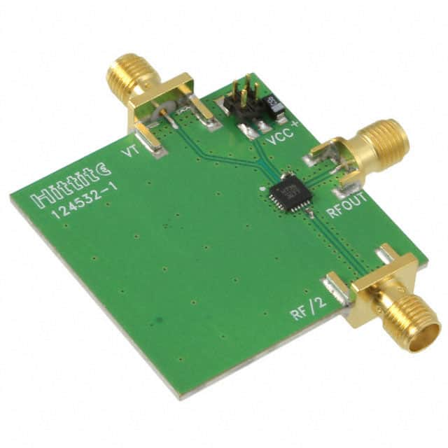
The HMC736LP4E is a GaAs MMIC voltage-controlled oscillator (VCO) with integrated prescaler, packaged in a 4x4 mm QFN and mounted on the EVAL board with SMA connectors and bias network. Most customer failures I see are not the die itself but the power sequencing, thermal path, or 50-ohm environment around it. Start by treating the EVAL board as a reference layout, not a drop-in module.
Typical failure modes and root causes. Dead output with correct DC bias usually means the VCO core was damaged by an over-voltage or reverse transient on Vcc, since the HMC736 tolerates only a narrow supply window. A second common mode is a locked or drifted frequency: the tuning line is being loaded by a low-impedance source, or the bypass capacitor on VTUNE is missing, allowing noise to pull the oscillator. Reduced output power with a clean spectrum often points to a bad SMA solder joint or a damaged internal amplifier stage from ESD. Finally, elevated phase noise that looks like the part is "noisy" is usually the ground return: the exposed pad must be soldered to a solid RF ground plane with multiple vias, and on a hand-soldered EVAL board a cold paddle joint is easy to create.
Step-by-step debugging methodology. First, apply Vcc with a current-limited bench supply set to the datasheet nominal and watch the quiescent current. If current is near zero, the part is likely dead or the bias trace is open; if current is far above spec, stop immediately. Second, verify the tuning voltage at the VTUNE pin with a high-impedance DMM or active probe, not a 10x passive probe that can load the node. Third, measure RF output on a spectrum analyzer with a 6 dB pad, sweeping VTUNE slowly across its range and recording frequency versus voltage. Fourth, if the output is absent, inject a known signal into the output port through a directional coupler to confirm the board's output path is intact. Fifth, isolate the VCO from downstream circuitry and repeat the measurement at the EVAL board SMA to rule out load pulling.
Common schematic and layout mistakes. The most frequent is inadequate decoupling: place 100 pF and 1000 pF capacitors directly at the Vcc and VTUNE pins, plus a bulk 10 uF nearby, or the oscillator will exhibit spurious sidebands. Another is running the tuning line as a long, thin trace next to digital or switching signals; this couples noise directly into the varactor. Do not forget the series resistor and bypass on the prescaler supply if you use it, and never leave the prescaler output floating if it is unused. On layout, the ground paddle must have a via array, not a single via, and the RF output trace should be a controlled 50-ohm coplanar waveguide with ground stitching on both sides. Poor thermal relief on the paddle causes frequency drift as the die heats.
Verifying authenticity and quality. Counterfeit HMC736LP4E parts show up as re-marked packages with inconsistent pin 1 orientation or laser-etched logos that smear under solvent. Buy only from authorized distributors and check the date code and lot against the Analog Devices traceability system. On the EVAL board, inspect the solder fillets under magnification: an authentic board has uniform, shiny joints and a clear silkscreen. Measure the DC resistance from each RF pin to ground; a short or very low resistance indicates a damaged die. If you have a known-good EVAL board, compare S-parameters and phase noise curves; a 6 to 10 dB discrepancy in phase noise is a strong authenticity red flag.
Measurement techniques and equipment. Use a spectrum analyzer with a phase noise option or a signal source analyzer for close-in noise, a calibrated power meter for absolute output, and a low-noise DC supply with a microamp meter for bias. A vector network analyzer is useful for checking the output match, but remember the VCO is not a linear two-port; keep the drive low. For tuning sensitivity, use a precision voltage source with <1 mV resolution and a frequency counter with a stable timebase. Always torque SMA connectors to the specified value and use a torque wrench; over-tightening cracks the launch and creates intermittent opens.
Component versus surrounding circuit. Suspect the HMC736LP4E itself only after you have verified clean DC bias, correct tuning voltage, a solid ground, and a 50-ohm load. If the part draws correct current, tunes monotonically, and shows the datasheet output power into a known load, the die is fine and the problem is downstream. Conversely, if the current is wrong or the frequency does not respond to VTUNE at all, the component is the prime suspect.
Real-world case studies. One customer reported 20 dB of extra phase noise on the EVAL board; the cause was a missing 100 pF bypass on VTUNE, replaced with a long wire to a bench capacitor. Adding the chip capacitor at the pin restored the datasheet curve. Another customer saw intermittent output dropouts; the root cause was a cold solder joint on the ground paddle, which opened as the board warmed. A third case involved a "dead" VCO that turned out to be a reversed supply from a miswired cable harness; the part was destroyed, and the replacement failed again until the harness was corrected. In each case, the EVAL board itself was sound, and the fault was in the test setup or assembly.