DD51 Mechanical Position Indicator Troubleshooting Guide (CE.95441-4N)
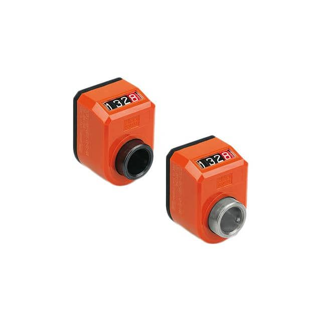
When customers call about the Elesa CE.95441-4N mechanical position indicator (often referenced under the DD51 family in legacy drawings), the first thing I tell them is that this is not an electronic component. It is a precision mechanical assembly with a rotating dial, gear reduction, and a windowed housing. Most "failures" are installation or misapplication issues, not defects. Understanding that distinction saves hours of unnecessary debugging.
Typical failure modes and root causes. The most common complaint is a stuck or erratic dial. Root causes include over-torquing the mounting nut, which distorts the housing and binds the internal gear train; debris ingress when the unit is mounted in a washdown area without the proper IP-rated variant; and shaft misalignment exceeding the manufacturer's tolerance. A second failure mode is incorrect readout—the dial advances but does not match the actual position. This is almost always a setup error: the user zeroed the indicator at the wrong reference point or selected the wrong gear ratio for the lead screw pitch. A third mode is physical damage to the window or dial face from impact or chemical attack. Polycarbonate windows craze when exposed to ketones or strong solvents.
Step-by-step debugging methodology. Start by disconnecting the indicator from the drive shaft. Rotate the input by hand through a full range. If it binds or feels gritty, the problem is internal—likely contamination or a damaged gear. If it rotates smoothly, the problem is in the coupling or the drive mechanism. Next, verify the gear ratio against the lead screw. For a 5 mm pitch screw, a 1:1 indicator will show one revolution per 5 mm of travel. If the customer expects 1 mm resolution, they need a 5:1 reduction. Third, check the zero reference. Loosen the dial set screw, rotate to the true zero position, and retighten. Do not force the dial past its mechanical stop.
Common mistakes in schematic design and PCB layout. This component has no electrical interface, so schematic errors are rare. However, mechanical integration drawings often omit the required clearance for the dial bezel. I have seen customers mount the indicator flush against a panel, only to find the dial cannot be read at an angle. Another mistake is specifying the wrong shaft adapter. The CE.95441-4N uses a specific bore and keyway; forcing it onto a mismatched shaft cracks the internal hub. In PCB terms, think of this as a footprint error—the mechanical equivalent of putting a 0402 pad under an 0603 part.
How to verify component authenticity and quality. Elesa USA ships units with a laser-etched logo and a batch code on the housing. Counterfeits often have painted logos that smear with solvent. Check the gear backlash: a genuine unit has minimal play, typically under 2 degrees at the input. Spin the input and listen—a healthy indicator is nearly silent. Grinding or clicking indicates damaged teeth. Also verify the window material. Genuine units use UV-stabilized polycarbonate; cheap substitutes yellow within months outdoors. If the customer bought through an unauthorized distributor, suspect a counterfeit immediately.
Measurement techniques and what test equipment to use. You need very little electronics gear here. A dial indicator with a magnetic base is your primary tool. Mount it against the input shaft to measure runout. A torque screwdriver verifies that mounting torque is within the specified range—typically 1.5 to 2.0 Nm for the mounting nut. A feeler gauge checks the gap between the dial and the housing. For electrical integration, a multimeter confirms that any proximity sensor used alongside the indicator is triggering at the correct position. An optical tachometer can verify that the dial revolutions match the drive speed if you suspect a gear ratio error.
When to suspect the component vs. the surrounding circuit. If the indicator rotates freely by hand but fails under load, suspect the coupling or the drive shaft, not the indicator. If the dial reads correctly at low speed but drifts at high speed, suspect backlash in the drive train or a worn coupling. Only suspect the indicator itself when it binds by hand, shows visible damage, or fails a backlash check. In my experience, fewer than one in twenty returns is an actual manufacturing defect.
Real-world case studies. A packaging customer reported that their indicators were failing every three months. Investigation showed they were using a high-pressure washdown with a caustic cleaner. The standard CE.95441-4N is not sealed for that environment. Switching to the IP67 variant solved the problem. Another case: a machine builder complained that the dial never matched the actual position. They had installed a 1:1 indicator on a 10 mm pitch ball screw and expected 0.1 mm resolution. The fix was a 10:1 reduction unit. A third case involved a counterfeit unit that stripped its gears within a week. The customer had purchased from an online marketplace. Buying through Elesa USA or an authorized distributor eliminated the issue.
In summary, treat the DD51/CE.95441-4N as a mechanical instrument. Verify installation torque, gear ratio, and environmental sealing before condemning the part. Most problems are solved with a torque wrench, a dial indicator, and a careful reading of the datasheet.