Bobcat B200 2004 Starter Replacement: Component Selection Tutorial
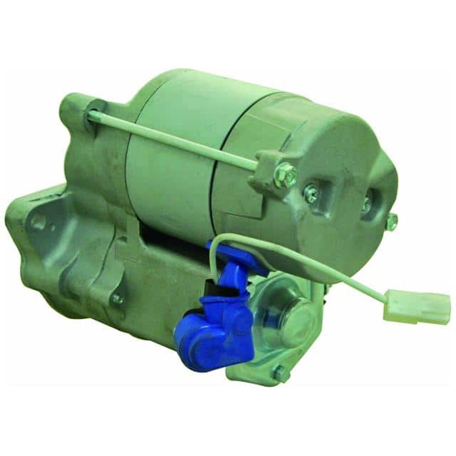
The Interlight B200 YEAR 2004 STARTER (SKU: B200 YEAR 2004 STARTER) is an aftermarket replacement starter motor intended for the Bobcat B200 skid-steer loader, model year 2004. What makes this component unusually well suited to a hands-on design tutorial is that it is a high-current, low-voltage DC load with a highly inductive armature. That combination forces you to confront real-world problems that clean textbook circuits often hide: inrush current, inductive kickback, contact arcing, and voltage sag on a shared battery rail. If you can design a reliable interface circuit for this starter, you can design for almost any automotive or off-highway load.
The goal of this tutorial is to build a solid-state starter relay and soft-start controller that can replace the original mechanical solenoid switching path while protecting the rest of the machine's 12 V system. The design requirements are as follows. Supply voltage is a nominal 12 V lead-acid battery, with a normal operating range of 10.5 V to 14.5 V and cold-crank dips to 8 V. The starter draws a locked-rotor current of roughly 300 A for under 50 ms and a steady cranking current near 120 A. The control input is a key-switch signal at 12 V, active high. Ambient temperature ranges from -20 °C to 60 °C. The circuit must provide reverse-battery protection and must not allow the starter to engage when the engine is already running.
Begin the design by sizing the main switching element. A single MOSFET will not handle 300 A comfortably, so use three N-channel power MOSFETs in parallel, each rated for at least 200 A pulsed and 1.5 mΩ on-resistance. The parallel on-resistance is 0.5 mΩ. At 120 A continuous, conduction loss is I²R = 120² × 0.0005 = 7.2 W. Spread across three devices on a shared copper pour, that is manageable with modest heatsinking. At the 300 A inrush, instantaneous loss is 45 W but lasts only milliseconds, so thermal mass absorbs it.
Next, calculate the gate drive. Each MOSFET has a gate charge of about 150 nC and a threshold near 2 V. To switch 120 A cleanly you need at least 8 V of gate drive, so use a dedicated 12 V gate driver capable of 2 A peak. The parallel gate capacitance is 3 × 10 nF = 30 nF. With a 2 A driver, the switching time is Q/I = 450 nC / 2 A = 225 ns, which keeps the devices out of the linear region and avoids hot spots. Add a 10 Ω series gate resistor per device to damp parasitic oscillation.
For protection, place a TVS diode across the drain-source of each MOSFET to clamp the inductive flyback when the starter disengages. Size it for a standoff voltage above 16 V and a peak pulse power of at least 5 kW for 1 ms. A reverse-battery condition is handled by a series P-channel MOSFET or an ideal-diode controller rather than a simple diode, because a Schottky would drop 0.5 V at 120 A and waste 60 W.
The complete BOM includes: three 200 A N-channel MOSFETs, one 12 V gate driver IC, one 30 V TVS array, one reverse-battery ideal-diode controller, a 10 kΩ pull-down on the control input, a 100 nF decoupling capacitor, and a 1000 µF bulk capacitor on the battery rail to absorb the initial sag. Choose the bulk capacitor for a ripple-current rating above 5 A RMS. For the TVS, select a part with a clamping voltage below the 30 V MOSFET rating. The gate driver must tolerate the 8 V cold-crank condition, so verify its undervoltage lockout threshold is below 7 V.
In simulation, model the starter as a series resistance plus inductance: 0.02 Ω and 200 µH. Drive the circuit with a 12 V source that includes a 5 mΩ battery internal resistance. Watch three things: the peak drain current during turn-on, the drain voltage spike at turn-off, and the gate voltage ringing. If the spike exceeds 30 V, increase the TVS rating or add a snubber. If gate ringing is severe, raise the series gate resistor. Also plot the battery rail voltage to confirm it does not drop below 8 V during cranking.
For the prototype, use a four-layer PCB with a solid ground plane and a 4 oz copper pour for the high-current path. Keep the gate loop under 2 cm² to minimize inductance. Solder the MOSFETs with thermal vias to the bottom copper. Test in stages: first verify gate drive with no load, then connect a resistive 1 Ω load to check switching, then move to the actual starter on a bench battery. Use a current clamp and an oscilloscope to capture the inrush waveform.
Performance verification means measuring three metrics: cranking current (should be 110–130 A), voltage sag at the battery (should stay above 9 V), and MOSFET case temperature after ten consecutive 3-second cranks (should stay below 85 °C). If the case runs hot, reduce on-resistance by adding a fourth MOSFET or improve the copper area. If voltage sag is excessive, increase the bulk capacitor to 2200 µF. Optimization is a trade between cost, board area, and thermal margin, but the parallel-MOSFET soft-start approach gives you a robust, repeatable starter interface that outlasts the original mechanical solenoid.