Ushio 048777127025 (WW-FK77-7) Application Note: Design & Integration Guide
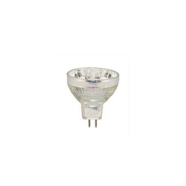
The Interlight WW-FK77-7, cross-referenced to USHIO 048777127025, is a lamp assembly typically used in projection, industrial imaging, and specialty lighting applications. Designing it into a new system requires attention to its electrical drive characteristics, thermal environment, and mechanical interface. Treat this component as a hot-swappable, high-current load with a non-linear impedance profile rather than a simple resistive element. The lamp's ignition phase draws a brief, high-voltage strike pulse, followed by a low-voltage, high-current arc that must be regulated to avoid electrode erosion and premature failure. Your circuit topology should therefore separate the igniter function from the steady-state ballast function.
For recommended circuit topologies, use a two-stage approach: a boost converter followed by a buck or flyback current regulator. The boost stage raises the input rail (typically 12 V to 24 V DC) to a level sufficient for the igniter, often 300 V to 400 V. The igniter itself should be a series-resonant tank driven by a half-bridge or a dedicated pulse transformer with a spark-gap or SCR crowbar. Once the arc strikes, the controller must transition within 10 to 50 milliseconds from open-loop high-voltage strike mode to closed-loop constant-current regulation. A current-mode PWM controller with a soft-start ramp and a strike-detection comparator is ideal. Avoid simple resistor-ballast designs; they waste power and cannot maintain stable current as the lamp warms and its impedance drops.
Component selection for supporting passives is critical. For the boost inductor, choose a ferrite core with a saturation current at least 1.5 times the peak switch current and a low DC resistance (under 50 mΩ) to minimize heating. The output capacitor after the boost stage must handle the igniter's high-voltage transients; use a polypropylene film capacitor rated for at least 630 V DC in parallel with a low-ESR electrolytic. For current sensing, a 0.01 Ω to 0.05 Ω four-terminal Kelvin shunt is preferred over Hall-effect sensors for its lower drift and faster response. Gate drive resistors should be 2 Ω to 5 Ω to control switching slew rates, and snubbers (RC or RCD) across the main switch are mandatory to clamp inductive kickback from the lamp leads. Do not use standard aluminum electrolytics for the igniter energy storage; their ESR rises sharply at the strike frequencies (20 kHz to 100 kHz) and can cause misfires.
PCB layout must minimize loop areas for both the high-current arc path and the high-voltage strike path. Place the boost inductor, main switch, and output capacitor in a tight cluster with a ground plane directly beneath them. The lamp return current should not share the same copper trace as the control ground; use a star ground with a single tie point at the shunt's Kelvin terminals. Route the igniter output traces as a twisted pair or parallel traces with 2 mm to 3 mm spacing to reduce radiated magnetic fields. Keep the high-voltage strike traces at least 5 mm away from any logic or analog signal lines, and never route them under the microcontroller or current-sense amplifier. For the lamp connector, use a dedicated high-voltage rated terminal block with a creepage distance of at least 8 mm between pins. Add a guard ring around the current-sense amplifier input to shunt leakage currents.
EMC/EMI mitigation starts with the switching node. Use a shielded inductor or a toroidal core for the boost stage, and add a common-mode choke on the DC input lines rated for the full load current. Place a 100 nF X7R ceramic capacitor directly across the lamp terminals to snub the arc's high-frequency noise, but verify it does not degrade strike performance; if it does, use a series 10 Ω resistor. The igniter's pulse transformer should have a copper foil shield connected to the primary-side ground. For conducted emissions below 30 MHz, add a differential-mode pi filter (10 µH inductor plus two 1 µF ceramics) on the input. For radiated emissions, keep all high dv/dt traces short and consider a small aluminum shield can over the igniter section, grounded at multiple points. Always test with the lamp installed and at end-of-life (aged lamp) because the arc's noise signature changes as the electrodes degrade.
Common design pitfalls include insufficient strike voltage margin (the lamp may require 1.5 times the nominal strike voltage when cold), current overshoot during strike-to-run transition (which pits the electrodes), and thermal runaway in the current-sense resistor if it is undersized. Another frequent mistake is using a single-point ground for the high-current return and the igniter return; this creates a ground loop that can falsely trigger the strike detector. Also, do not assume the lamp's impedance is constant; it drops by 20% to 30% as it warms, so your current regulator must have enough headroom to maintain regulation at the minimum lamp voltage. Finally, avoid mounting the lamp socket directly to a metal chassis without an insulating washer; the lamp's base can be at a high potential during strike.
For prototyping, start with a bench power supply current-limited to 1.2 times the expected run current and a dummy load (a 10 Ω to 30 Ω, 100 W resistor in series with a 1 mH inductor) to verify the ballast's regulation before connecting the actual lamp. Use a high-voltage differential probe (1000:1) to observe the strike pulse and a current probe (Pearson or Rogowski) to capture the arc current waveform. Test the strike-to-run transition at least 50 times, measuring the peak current and the time to reach steady state. For thermal testing, run the lamp at full power for 30 minutes in a 40°C ambient and measure the case temperature of the boost inductor, the main switch, and the shunt; derate any component that exceeds 80% of its rated temperature. Always include a fuse or electronic breaker in series with the lamp return, rated for 2 times the run current, to protect against a shorted lamp or a failed igniter. Log the strike voltage and run current over the lamp's life to establish a replacement threshold.