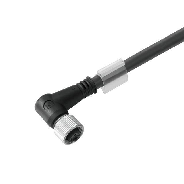
SENSOR-ACTUATOR CABLE M1 12POLE 1424280150 Datasheet Guide Explained
When evaluating the Weidmüller sensor-actuator cable identified by SKU 1424280150, engineers must first recognize that this is not a semiconductor device with a traditional datasheet full of junction temperatures and switching losses. Instead, it is a passive interconnect assembly—specifically an M12 12-pole cordset—and its "datasheet" is a specification sheet defining mechanical, environmental, and electrical limits. The most critical electrical parameter is the rated voltage per contact, typically 30 V AC/DC for signal-level M12 connectors, though some 12-pole variants support 60 V or higher depending on insulation and creepage distances. In practice, this means the cable is intended for low-voltage sensor and actuator loops, not for direct mains power or motor drive circuits. The rated current per contact usually falls between 1.5 A and 4 A, with the lower figure applying when all 12 poles are simultaneously loaded. This derating behavior is non-negotiable: if only two or three poles carry current, the per-contact limit may rise slightly, but the datasheet will specify a single conservative value. Engineers must also note the contact resistance, often specified as ≤ 10 mΩ, which directly affects voltage drop in long cable runs. For a 5-meter cable carrying 2 A, even 20 mΩ total loop resistance yields a 40 mV drop—acceptable for most 24 V sensor circuits but significant for precision analog signals.
Absolute maximum ratings for this cable are less about catastrophic failure and more about irreversible degradation. The maximum continuous current must never be exceeded because sustained overcurrent will heat the contact springs, reduce normal force, and increase contact resistance in a runaway thermal cycle. The maximum voltage is limited by the dielectric strength of the thermoplastic insulator and the air gap between pins. Exceeding this rating risks arc-over, especially in humid or contaminated environments. Derating considerations are dominated by ambient temperature. A typical Weidmüller M12 cable is rated for -40 °C to +85 °C, but the current-carrying capacity decreases above 40 °C. For example, at 70 °C, the allowable current might drop to 60% of the 25 °C rating. The datasheet may provide a derating curve, but if not, a linear derating from full current at 40 °C to zero at the maximum insulation temperature (often 105 °C for PVC, 125 °C for PUR) is a safe engineering approximation. Mechanical derating also applies: repeated flexing reduces the strand integrity, so the minimum bend radius—typically 5× to 10× the cable diameter for fixed installation and 10× to 15× for continuous flex—must be respected to avoid conductor fatigue.
In a typical application circuit, this 12-pole cable serves as the physical layer between a control cabinet I/O module and a remote sensor-actuator junction. Consider a distributed I/O system where the cable carries eight digital sensor inputs (24 V DC, 5 mA each), two analog outputs (0–10 V, 20 mA), and two power conductors for a local actuator (24 V DC, 1.5 A). The total current through the common return path can approach 1.6 A, which is within the per-contact rating only if the return is split across multiple pins. A common mistake is to use a single return pin for all loads, which concentrates current and creates a voltage gradient along the cable. The datasheet’s conductor cross-section—often 0.14 mm² to 0.25 mm² for signal pins and 0.5 mm² for power pins—determines the IR drop. For a 10-meter run at 1.5 A, a 0.5 mm² copper conductor has about 0.35 Ω per 10 meters, giving a 0.5 V drop. That is marginal for a 24 V actuator that requires 21.6 V minimum. The solution is either to use a shorter cable, a larger cross-section variant, or to parallel multiple pins for power and return. The datasheet will not tell you how to parallel pins, but it will give the current per pin and the temperature rise, from which you can calculate the safe parallel count.
Pin configuration for a 12-pole M12 connector follows IEC 61076-2-101. The pins are numbered 1 through 12 in a circular arrangement, with a keyway to prevent mis-mating. The datasheet provides a contact arrangement drawing and a wiring table that maps each pin to a wire color or number. Engineers must pay close attention to whether the cable is shielded. If it is a shielded variant, the shield is typically connected to the metal coupling nut, which must be bonded to chassis ground at one end only to avoid ground loops. The package considerations are mechanical: the cable diameter (typically 6 to 8 mm), the coupling nut material (usually nickel-plated brass or stainless steel), and the sealing class (IP65, IP67, or IP68). An IP67 rating means the connector can survive temporary immersion, but only if the mating counterpart is also IP67 and the coupling nut is torqued to the specified value—often 0.4 to 0.6 Nm. Over-torquing cracks the insulator; under-torquing allows water ingress.
Thermal management for this passive cable is straightforward but often ignored. The primary heat sources are the I²R losses in the conductors and the contact resistance at the mating interface. At 2 A per contact with 10 mΩ contact resistance, each pin dissipates 40 mW. Twelve pins dissipate 480 mW total, which is negligible for a cable in free air. However, when the cable is bundled with other cables in a tight conduit, the ambient temperature rise can be 20 °C or more. The datasheet’s temperature derating curve accounts for this by reducing the current rating as ambient rises. If no curve is given, use the insulation temperature limit: for PVC, 105 °C; for PUR, 125 °C. The maximum continuous current at 25 °C ambient is typically rated to produce a 30 °C rise. So if the insulation limit is 105 °C, the maximum ambient is 75 °C. Above that, you must reduce current. Forced air cooling is rarely practical for a cable, so the only options are larger cross-section, shorter length, or fewer loaded pins.
Finally, timing diagrams and characteristic curves in a cable datasheet are not about propagation delay—they are about mechanical and environmental performance. The most common curve is current versus ambient temperature, which is a descending line from full rated current at 40 °C to zero at the insulation limit. Another curve may show contact resistance versus mating cycles, starting at 5 mΩ and rising to 20 mΩ after 100 cycles. A third curve might plot cable capacitance versus length, which matters for high-speed digital signals. For example, a 10-meter cable with 50 pF/m capacitance presents 500 pF, which can slow a 1 MHz square wave. The datasheet may also include a pull-out force specification, typically 100 N minimum, which ensures the cable does not disconnect under vibration. When reading these curves, always check the test conditions: temperature, humidity, and whether the cable was flexed or static. A curve measured on a static cable in a laboratory will overstate performance in a continuous-flex drag chain application. The engineer’s job is to apply a safety margin—typically 50% derating on current and 20% on temperature—to account for real-world worst-case conditions.