FK23L Immersion/Penetration Probe Application Note: Setup and Best Practices
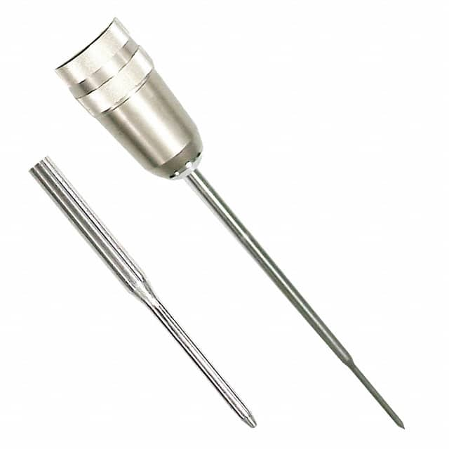
The TPI FK23L immersion/penetration probe is a temperature-sensing accessory built around a type-K thermocouple junction housed in a stainless steel sheath with a handle and cable assembly. Design engineers typically encounter it as the sensing element for a handheld meter, a data logger front end, or an embedded temperature-monitoring channel. Because the probe itself is passive, the design work concentrates on the cold-junction compensation (CJC) network, the input protection, the analog front end, and the physical routing of the probe cable into the enclosure. The FK23L is intended for direct contact with liquids, semi-solids, and penetrable materials, so the electrical design must tolerate a long, unshielded or lightly shielded two-wire lead that behaves like an antenna in a noisy environment.
For the sensing front end, the two dominant topologies are the instrumentation-amplifier approach and the thermocouple amplifier IC approach. An INA or similar low-offset, low-drift instrumentation amplifier configured for a gain of roughly 100 to 250 works well when the type-K output (about 41 µV/°C) must be resolved to 0.1 °C. A more compact and often more accurate option is a dedicated thermocouple amplifier such as the MAX31855, MAX6675, or AD8495, which integrates the cold-junction sensor and linearization. In either case, place the CJC sensor—whether an on-chip junction, a remote diode, or a precision thermistor—as close as physically possible to the point where the probe's two thermocouple wires terminate on the PCB. Any thermal gradient between that terminal block and the CJC sensor becomes a direct temperature error. Best practice is to keep the terminal block and CJC sensor on an isothermal copper island, isolated from heat-generating components and from airflow that would cool one side preferentially.
Supporting passives deserve careful selection. Use 1% or better metal-film resistors with a low temperature coefficient (25 ppm/°C or tighter) for the gain-setting network, because resistor drift translates directly into gain error. For the input filter, a differential RC with a 100 nF to 1 µF C0G/NP0 capacitor and matched 1 kΩ to 10 kΩ series resistors suppresses RF pickup while adding negligible thermal EMF. Avoid X7R or Y5V dielectrics in the signal path; their voltage and temperature coefficients introduce nonlinearity. The reference, if used, should be a low-drift type such as a buried-zener or a precision series reference. Bypass all analog supply pins with 100 nF C0G plus 1 µF to 10 µF bulk capacitance, and consider a small series ferrite on the analog supply rail if the board shares a rail with switching regulators.
PCB layout follows the standard low-level analog rules but with extra attention to thermal symmetry. Route the two thermocouple traces as a tight differential pair of equal length from the terminal block to the amplifier inputs, and keep them away from clock lines, switch-node traces, and any high-current return paths. Do not route them under or near the switching regulator inductor. Keep the analog ground plane continuous beneath the front end and connect it to the digital ground at a single point near the ADC or amplifier. Guard the high-impedance input nodes with a ground ring tied to the analog ground. Because the FK23L cable may be a meter or more long, treat the connector entry point as an EMC boundary: place a common-mode choke or a small ferrite bead on the probe leads right at the enclosure entry, and add transient clamps such as low-capacitance TVS diodes or a bidirectional clamp rated for the expected ESD and surge levels. The probe's stainless sheath is electrically floating, so it provides no shielding; if the application is electrically noisy, consider a shielded extension cable with the shield terminated to chassis ground at the instrument end only.
EMC and EMI mitigation should be designed in from the start. The most common failure mode is RF rectification at the amplifier input, which appears as a slow DC offset drift. A differential input filter with a corner frequency around 1 to 10 kHz, combined with a common-mode choke, handles most conducted and radiated susceptibility testing. For emissions, the thermocouple leads can act as an unintended antenna; keep loop areas small, and if the product must pass radiated emissions, add a ferrite sleeve or a small common-mode choke at the cable exit. Ground the enclosure to the analog ground at one point and avoid creating ground loops through the probe cable shield. If the instrument is battery powered, this is usually straightforward; if it is mains powered, pay attention to the isolation barrier and keep the thermocouple front end on the isolated side.
Common pitfalls include ignoring thermal EMF at solder joints and connectors, which can add tens of microvolts and thus several tenths of a degree of error; using unmatched input filter components, which converts common-mode noise into differential error; and placing the CJC sensor where it sees a different temperature than the terminal block. Another frequent mistake is assuming the FK23L is interchangeable with other type-K probes without recalibration—probe-to-probe tolerance and the meter's own CJC accuracy both contribute. Also avoid over-filtering the input to the point where the response time becomes unacceptable for the measurement, and never connect the probe to a live circuit expecting isolation unless the instrument explicitly provides it.
For prototyping, build the front end on a small board with a generous ground plane and a screw terminal for the probe, then verify with an ice bath (0 °C) and boiling water (adjusted for local barometric pressure) before trusting any reading. Use a precision thermocouple simulator or a millivolt source to sweep the input and confirm gain and offset. Bench-test the assembly with the probe cable coiled and stretched, near a switching supply and a handheld radio, to expose rectification and pickup problems early. Log the output over time with the probe at a stable temperature to check drift, and compare against a reference thermometer. These steps catch the majority of integration issues before the design reaches EMC qualification.