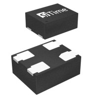
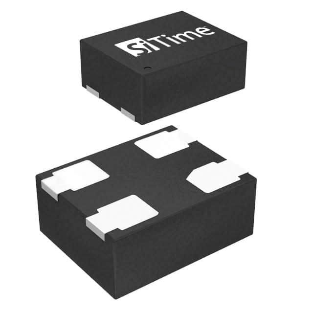
Application Note: SIT8924BE MEMS Oscillator 24MHz LVCMOS Design Guide
The SiTime SIT8924BE-78-33N-24.000000 is a 24.0000 MHz MEMS-based silicon oscillator delivering LVCMOS output from a nominal 3.3 V supply. Unlike a quartz crystal, this device integrates the resonator and the oscillator circuitry in a single package, so your job as a design engineer is not to build a pi-network or tune load capacitors but to provide a clean supply, a solid ground reference, and a controlled transmission path. The recommended topology is a simple point-to-point connection: VDD to the positive rail through a local decoupling network, GND to the ground plane, and the output pin driving the clock input of your downstream device. Because the part is factory-programmed, no external frequency-setting components are needed, and the output enable or standby pin (depending on the exact option code) should be tied to a defined logic level rather than left floating. If your downstream receiver has a high-impedance or capacitive input, place a series termination resistor close to the oscillator output; values in the 22 to 33 ohm range are typical for 50 ohm traces, and this resistor also softens the output edge, which directly reduces radiated harmonics.
Supporting passives are few but not unimportant. For the supply, use a 0.1 µF X7R or C0G ceramic capacitor placed within a few millimeters of the VDD pin, plus a bulk capacitor of 1 to 10 µF on the same rail to absorb lower-frequency transients. Keep the ESR of the bulk capacitor reasonable; very low ESR electrolytics can interact with the regulator, so a ceramic or polymer part is usually the better choice. If the oscillator shares a rail with switching regulators, ADCs, or high-current digital logic, add a ferrite bead or a small series inductor between the noisy rail and the oscillator's local decoupling network. The output series resistor, if used, should be a standard 1% thick-film part with low parasitic inductance; avoid wirewound types. Do not add pull-up or pull-down resistors on the clock output unless the downstream input genuinely requires them, since LVCMOS push-pull outputs do not need external biasing and extra loading only increases current draw and edge degradation.
PCB layout for a MEMS oscillator is straightforward but rewards discipline. Place the device on the same layer as the receiving IC whenever possible, keep the clock trace short and direct, and route it over an uninterrupted ground plane. Treat the clock line as a controlled-impedance trace; for typical FR-4 and a 24 MHz fundamental with fast edges, a 50 ohm microstrip is a sensible target. Never route the clock trace parallel to or underneath noisy signals such as switch-mode nodes, USB differential pairs, or high-speed data buses; if crossing is unavoidable, cross at right angles on different layers with a ground plane between them. Keep the return path continuous—any slot or split in the ground plane beneath the clock trace will force return current to detour and radiate. Avoid vias in the clock path when possible; each via adds inductance and a small impedance discontinuity. Thermal relief is generally unnecessary for this package, so connect the ground pad directly to the plane with multiple vias for both electrical and thermal integrity.
EMC performance starts with edge rate control. The SIT8924 family is designed with programmable drive strength, and the lowest drive setting that still meets your receiver's setup and hold margins will produce the lowest harmonic content. A series termination resistor at the source is the single most effective mitigation for clock-related emissions because it slows the edge and reduces ringing. If your product must pass strict radiated emissions limits, consider a small RC snubber or a ferrite bead in series with the clock line, but verify signal integrity afterward—added series impedance can degrade rise time and cause duty-cycle distortion. Keep the oscillator's ground return local and low-impedance; a poor ground connection turns the package into an unintended antenna. Shielding is rarely needed for a single 24 MHz LVCMOS clock, but if the trace must run a long distance, a ground guard trace or a grounded coplanar waveguide structure can help contain the field.
Several pitfalls appear repeatedly in designs using this part. First, engineers sometimes assume a crystal-style load capacitor is required; it is not, and adding capacitance to the output will degrade edges and increase jitter. Second, leaving the enable or standby pin floating can cause the output to toggle unpredictably or draw excess current, so always tie it to a defined level. Third, placing the decoupling capacitor on the far side of a via or several millimeters away defeats its purpose; the loop area between VDD, the capacitor, and GND must be minimal. Fourth, using a long, uncontrolled clock trace with no series termination invites reflections that can double-clock a sensitive receiver. Finally, powering the oscillator from a noisy rail without filtering is a common cause of elevated phase jitter and intermittent system failures.
For prototyping, start with a breakout board or an evaluation fixture that preserves a solid ground plane and short traces. Verify the supply voltage at the VDD pin with an oscilloscope, not just at the regulator output, and confirm the output frequency and amplitude with a high-impedance probe. Measure rise and fall times, duty cycle, and overshoot at the receiver input, not just at the oscillator pin, since the trace and load shape the waveform. Use a spectrum analyzer or a near-field probe to check for unexpected harmonics before committing to a production layout. If you observe jitter or frequency pulling, first suspect the supply and ground, then the output loading, and only then the oscillator itself. A simple bench test with a clean linear supply, a short coax connection, and a 50 ohm scope input will quickly confirm whether the device is behaving as specified.