Application Note: Class 5000 Meter 277/480V 400A E50-480400-J06NSPKIT
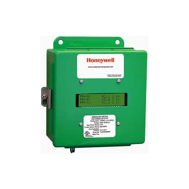
The Honeywell E50-480400-J06NSPKIT is a Class 5000 revenue-grade electrical meter designed for three-phase 277/480 V applications up to 400 A. Unlike a simple panel ammeter, this device combines voltage and current sensing, metering computation, and communication in a single package, so treating it as a drop-in replacement for a legacy analog meter will lead to problems. The meter is intended for direct connection on 277/480 V systems where the neutral is reliably referenced, and it expects the installer to provide external current transformers (CTs) unless the specific configuration includes internal CTs. In most designs, the meter is wired in a three-phase four-wire wye configuration, with each phase voltage tapped through a dedicated disconnect or fuse and each phase current routed through a CT whose secondary terminates at the meter's current input terminals. A common alternative is a three-phase three-wire delta topology, but this requires careful attention to the meter's configuration registers and may reduce accuracy because the meter's internal phase-angle compensation assumes a wye reference. Best practice is to use the meter only in the topology for which it is configured at the factory or explicitly reconfigured via the setup interface, and to keep the voltage and current paths physically separated until they reach the meter terminals.
Supporting passives are not optional accessories; they determine whether the meter meets its accuracy class in the field. For voltage inputs, use fused disconnects rated for the system voltage and interrupt capacity, and place a metal-oxide varistor (MOV) or transient voltage suppressor across each phase-to-neutral input to clamp surges before they reach the meter's internal divider network. Choose MOVs with a clamping voltage at least 20 percent above the nominal 277 V RMS to avoid conduction during normal operation, and verify their energy rating against the expected surge environment. For current inputs, the CT secondary wiring should be twisted pair with a characteristic impedance matched to the meter's burden, typically 0.1 to 0.2 VA per phase. Do not leave a CT secondary open-circuited under load; this produces dangerous voltages. If the meter is more than a few meters from the CTs, calculate the loop resistance and confirm it does not exceed the CT's rated burden. For the meter's power supply, use a dedicated branch circuit with a slow-blow fuse or a Class 2 supply if the meter accepts low-voltage auxiliary power, and add a 0.1 µF ceramic bypass capacitor plus a 10 µF electrolytic capacitor close to the supply pins to suppress conducted noise.
PCB layout is less about the meter itself, which is a packaged assembly, and more about the interface board that carries the CT burden resistors, voltage dividers, and communication transceivers. Keep the voltage sensing traces short and symmetric across phases so that parasitic inductance does not create phase-angle errors. Route current input traces as differential pairs with matched lengths and a ground plane underneath, and avoid running them parallel to switching power supply traces or relay drive lines. Place burden resistors as close to the meter's current terminals as possible, and use Kelvin connections if the resistor is a four-terminal type. For communication interfaces such as RS-485 or Modbus, use a dedicated transceiver with failsafe biasing and a 120 ohm termination resistor at each end of the bus. Keep the communication ground referenced to the meter's signal ground, not to the power ground, and if isolation is required, use a digital isolator with a rated working voltage exceeding the system's transient overvoltage category. Finally, provide a solid chassis ground connection to the meter's ground terminal using a star washer and a short, low-inductance strap.
EMC and EMI performance in a 480 V industrial environment depends on both the meter's internal filtering and the external wiring practices. The meter is tested to relevant IEC 62052-11 and IEC 61326 standards, but those tests assume a defined installation. To meet them in practice, use shielded twisted pair for CT secondaries and terminate the shield at the meter end only to avoid ground loops. Install a line reactor or ferrite bead on the auxiliary power input if the meter shares a circuit with variable-frequency drives or other noisy loads. For radiated emissions, keep the meter and its wiring away from high-frequency switching nodes, and if the enclosure is metallic, bond the meter's ground to the enclosure at a single point. For immunity, add a transient voltage suppressor across the auxiliary power input and use common-mode chokes on the communication lines. Do not rely on the meter's internal protection alone; external surge protection is cheap insurance for a revenue meter that may be difficult to replace.
Common design pitfalls include open-circuited CT secondaries, which can destroy the meter's current input stage and create a shock hazard; reversed CT polarity, which causes negative power readings and incorrect energy accumulation; and misconfigured CT ratios, which produce scaling errors that are not obvious until billing reconciliation. Another frequent mistake is using the meter's voltage inputs as a power source for other loads, which overloads the internal divider and degrades accuracy. Avoid mixing CTs from different manufacturers or with different accuracy classes on the same meter, because the meter's calibration assumes matched phase response. Also, do not ignore the meter's warm-up time; revenue-grade accuracy is typically specified after 30 minutes of powered operation, so bench tests performed immediately after power-up may show errors that disappear later.
For prototyping, build a low-voltage three-phase test bench using a 277/480 V variac or a three-phase transformer with a grounded wye secondary, and use precision resistive loads or a calibrated three-phase power source rather than motors. Verify the meter's voltage and current readings against a reference meter at 10 percent, 50 percent, and 100 percent of rated current, and check phase angle accuracy with a phase shifter if available. Before connecting to a live 480 V system, perform an insulation resistance test on all wiring with the meter disconnected, and verify CT polarity with a DC injection test or a known load. During bench testing, monitor the communication interface for CRC errors and check that the meter's configuration registers match the actual CT ratio and system voltage. Finally, document the exact wiring, CT model, and configuration settings for each installation, because troubleshooting a revenue meter without that record is unnecessarily difficult.