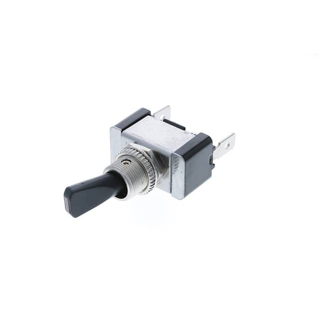
SP OFF-ON Blue LED M12X0.75 Switch TA1A-1A-DC-1-UL Application Guide
The TA1A-1A-DC-1-UL from Switch Components is a single-pole, OFF-ON illuminated pushbutton switch with a blue LED indicator, housed in an M12x0.75 threaded body. Because the LED is a separate electrical node from the switch contacts, the designer has full freedom to wire the illumination independently of the load path. The most common topology places the switch contacts in series with the load on the high side, with the LED anode tied through a current-limiting resistor to the same supply rail and the cathode returned to ground. This keeps the lamp lit whenever power is present, which is often desirable for panel indicators, but it means the LED does not necessarily reflect the true state of the load if the switch is wired in parallel with another control path. For applications where the LED must indicate actual load energization, wire the LED in parallel with the load after the switch contacts, or use a second pole if available. In low-side switching configurations, remember that the LED return must be referenced to the same ground as the control logic; floating returns are a frequent source of erratic illumination.
Selecting supporting passives begins with the LED forward voltage and current. Blue LEDs typically exhibit a forward drop between 2.8 V and 3.4 V, and the datasheet-recommended operating current is usually 10 mA to 20 mA. For a 12 V supply, a series resistor of roughly 470 Ω to 680 Ω will set the current near 15 mA; for 24 V systems, 1 kΩ to 1.2 kΩ is appropriate. Always calculate the resistor value using the worst-case minimum supply voltage and the maximum LED forward voltage to guarantee adequate brightness, then verify power dissipation at maximum supply. A 0.25 W resistor is usually sufficient, but derate for high ambient temperatures. If the supply is noisy or inductive, place a 100 nF ceramic capacitor across the LED and a reverse-protection diode or TVS across the switch contacts to clamp inductive kickback from relay coils or solenoids. For the switch contacts themselves, the TA1A series is rated for low-level switching, so do not exceed the contact current rating when driving lamps or motors directly; use an intermediate relay or MOSFET for loads above the contact rating.
PCB layout for the switch is straightforward because the M12 threaded body mounts to the panel, but the wiring to the board deserves attention. Keep the LED current loop small: route the resistor close to the switch pin, and return the cathode to a local ground plane rather than a long trace back to the power entry. If the switch is panel-mounted and connected via a harness, twist the LED anode and cathode wires together to reduce loop area and minimize radiated emissions. For the contact side, route the load current away from sensitive analog or high-impedance nodes. When the switch carries a inductive load, place the flyback diode as close as possible to the load, not at the switch, so the transient loop does not couple into the LED wiring. Use a solid ground plane under the switch connector footprint if the board is dense, and avoid running high-speed digital traces beneath the LED resistor or switch pins.
EMC and EMI considerations are modest for a panel switch, but the LED wiring can act as an antenna if it is long and unshielded. The blue LED is a diode and therefore nonlinear, so it can rectify RF pickup and cause visible flicker or false illumination in strong fields. A small ceramic capacitor (100 nF to 1 µF) across the LED, placed at the switch terminals, shunts RF energy and is usually sufficient. If the switch is part of a system that must meet CISPR 25 or similar automotive standards, add a ferrite bead in series with the LED anode and keep the harness short and shielded if it exceeds a few inches. For the contact circuit, snubbers across the switch (RC or TVS) reduce arcing and conducted emissions when switching inductive loads. Remember that the switch housing is metal and threaded; bonding it to chassis ground can improve shielding but may also create a ground loop if the panel is not the same reference as the PCB ground. Test both bonded and floating configurations on the bench.
Common pitfalls include forgetting the LED polarity, which is easy to reverse because the switch body is symmetric, and using a resistor value calculated for nominal voltage rather than worst-case. Another frequent error is assuming the LED is internally connected to the switch contacts; it is not, so a design that expects the lamp to turn off when the switch opens will fail unless the LED is wired in series with the load. Over-torquing the M12 nut can crack the plastic housing or damage the internal contacts, so follow the manufacturer's torque specification, typically around 0.4 N·m to 0.6 N·m. Finally, do not exceed the switch contact rating with inrush currents from incandescent lamps or capacitive loads; use a relay for those cases.
For prototyping, wire the switch on a bench with a current-limited supply set to the nominal system voltage and a series ammeter to confirm LED current. Measure the voltage across the resistor and the LED to verify the forward drop and adjust the resistor if brightness is insufficient. Test the contact side with a resistive load first, then substitute an inductive load and observe the switching waveform with an oscilloscope to check for ringing or arcing. Thermal-test the switch at maximum ambient and maximum load for at least 30 minutes, and check the LED for color shift or dimming. If the design includes a panel cutout, verify the M12x0.75 thread engagement and that the nut and washer seat properly. A simple continuity test across the contacts in both positions, combined with a visual check of the LED, will catch most assembly errors before the unit is installed.