ERJ-14NF3321U Datasheet Guide: 3.32K Ohm 1% 1210 SMD Resistor Explained
The Panasonic ERJ-14NF3321U is a surface-mount thick film chip resistor in the 1210 (3225 metric) case size, offering a resistance of 3.32 kΩ with a tight ±1% tolerance and a power rating of 0.5 W at 70°C. When interpreting the datasheet for this device, the first specification to internalize is the resistance value itself. The "3321" in the part number encodes 3.32 kΩ using the E96 series notation—three significant digits followed by a multiplier, where the final digit indicates the number of zeros to append. The "F" denotes ±1% tolerance, a precision grade that places this resistor in the category suitable for feedback networks, voltage dividers, and current-sense applications where a 5% part would introduce unacceptable error. The 0.5 W rating in a 1210 footprint is notably high for this case size, achieved through Panasonic's thick film construction and careful thermal design of the terminations. In practice, this means the designer can dissipate more power per unit area than with a standard 0.25 W or 0.33 W 1210 resistor, but only if the PCB layout provides adequate copper area for heat spreading.
The absolute maximum ratings section of the datasheet must be read in conjunction with the derating curve, not in isolation. The ERJ-14NF3321U is rated for 0.5 W at ambient temperatures up to 70°C, but above that threshold the permissible power decreases linearly, reaching zero at the maximum operating temperature of 155°C. The limiting element voltage is typically 200 V for this series, meaning that even if the power dissipation calculation permits a higher voltage, the resistor must never see more than 200 V across its terminals. For a 3.32 kΩ part, 200 V would correspond to approximately 12 W, far exceeding the thermal limit, so voltage is rarely the binding constraint here—but it becomes critical in high-voltage divider strings. The maximum overload voltage, often specified as twice the limiting element voltage for short durations, applies only during transient events and must never be used for continuous operation. Engineers should also note the temperature coefficient of resistance, typically ±100 ppm/°C for this series, which means a 55°C rise from 25°C to 80°C will shift the resistance by roughly 0.55%, consuming more than half of the ±1% tolerance budget in precision applications.
In a typical application circuit, the ERJ-14NF3321U might serve as the upper resistor in a feedback divider for a switching regulator or as a load resistor in a low-power sensor bias network. Consider a non-inverting amplifier with a gain of 2: the feedback network could use a 3.32 kΩ resistor from output to inverting input and an identical 3.32 kΩ resistor from inverting input to ground. The 1% tolerance directly affects gain accuracy, and the tracking between two resistors of the same series and value will be excellent if they are placed adjacent on the PCB and experience the same thermal environment. In current-sense applications, the 3.32 kΩ value is less common because sense resistors are typically in the milliohm range, but this part could serve as the gain-setting resistor in the sense amplifier. The 0.5 W rating provides substantial margin in signal-level circuits, where dissipation is typically below 50 mW, but the designer should still verify that the voltage across the resistor does not exceed the limiting element voltage during fault conditions.
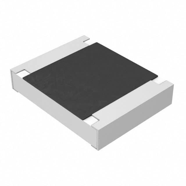
Pin configuration for a two-terminal chip resistor is trivial—there are no polarity or orientation constraints—but the package geometry matters for layout. The 1210 case size measures 3.2 mm by 2.5 mm, with termination widths that must be matched to the solder pad dimensions recommended in the datasheet's land pattern drawing. Using undersized pads increases the risk of tombstoning during reflow, while oversized pads waste board area and can lead to solder bridging in fine-pitch assemblies. The wrap-around terminations are typically nickel barrier with tin plating, compatible with both lead-free and tin-lead soldering processes. For automated placement, the component's mass and center of gravity are well within the capabilities of standard chip shooters, but the 1210 size may require a larger nozzle than 0402 or 0603 parts, so feeder setup and nozzle selection should be confirmed before production.
Thermal management guidelines for the ERJ-14NF3321U center on the PCB copper area connected to each termination. The datasheet's power derating curve assumes a certain thermal resistance from the resistor body to ambient, typically achieved with a recommended pad geometry on FR-4. If the actual copper area is smaller, the effective thermal resistance rises, and the resistor will operate hotter than the derating curve predicts. A useful rule of thumb is that doubling the copper area can reduce the temperature rise by 20–30%, but the relationship is not linear and depends on board thickness, copper weight, and the presence of thermal vias. In high-power-density designs, the resistor should be placed away from other heat sources and, if possible, on a copper plane that acts as a heat spreader. The 155°C maximum operating temperature provides a safety margin, but prolonged operation near that limit will accelerate resistance drift and may compromise long-term reliability.
Characteristic curves in the datasheet—such as power derating versus ambient temperature, resistance change versus load life, and thermal shock performance—should be interpreted as statistical representations, not guarantees for every individual unit. The load life curve, for example, typically shows a mean resistance shift of less than 1% after 1000 hours at rated power and 70°C, but the distribution around that mean is not always plotted. For mission-critical applications, the designer should derate further, perhaps to 50% of rated power, to stay well inside the curve's flat region. The thermal shock curve, often expressed as resistance change after 100 cycles from -55°C to +125°C, indicates the robustness of the termination and coating system. A flat response here suggests that the part will survive harsh environmental cycling without open-circuit failures, which is essential for automotive and industrial equipment. Reading these curves alongside the absolute maximum ratings and derating guidelines gives a complete picture of how the ERJ-14NF3321U will behave in the field, not just on the bench.